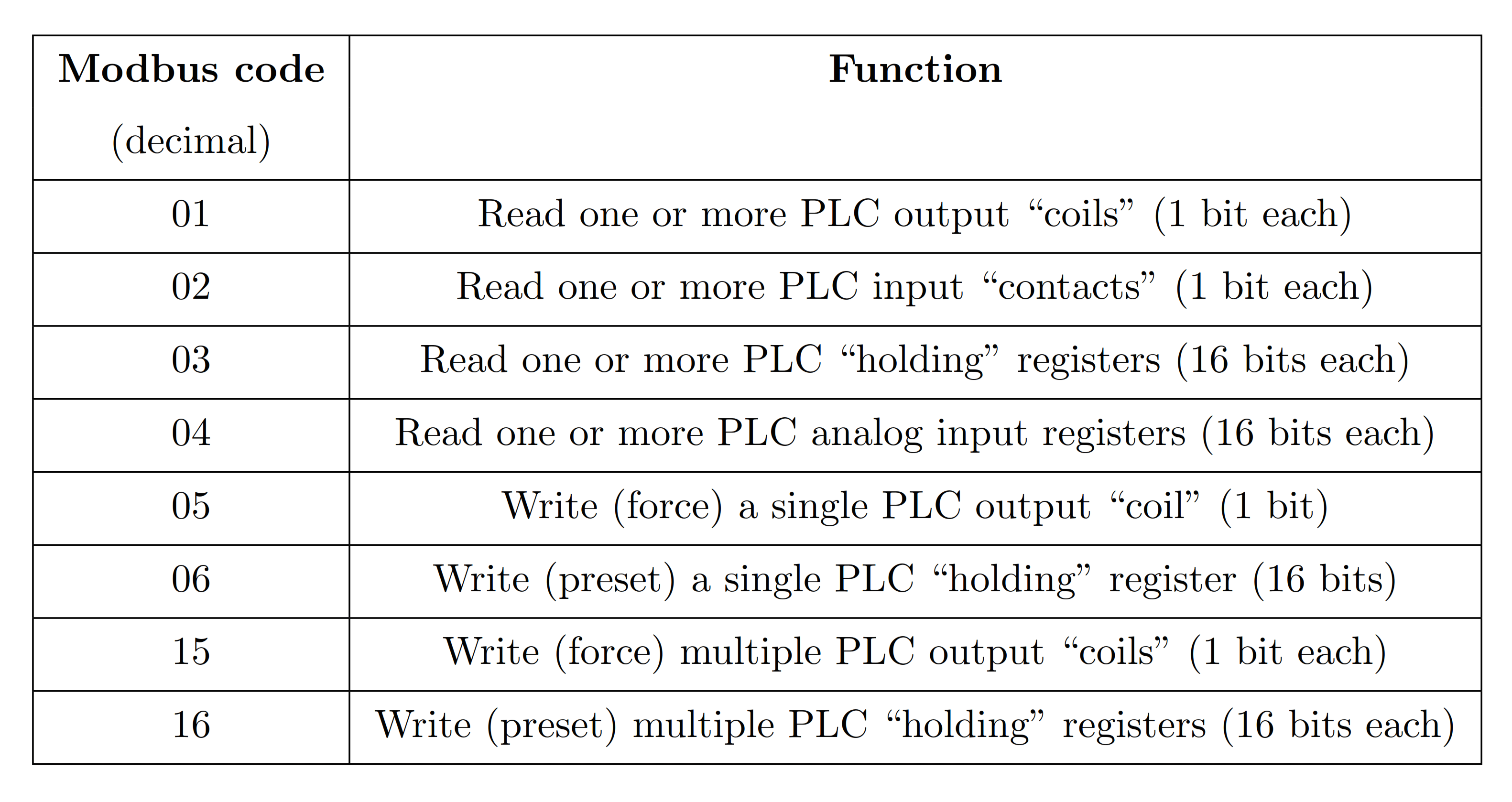
A listing of commonly-used Modbus function codes appears in the following table.
Modbus Function Codes
Live data inside of any digital device is always located at some address within that device’s random-access memory (RAM).
The Modbus “984” addressing standard defines sets of fixed numerical addresses where various types of data may be found in a PLC or other control device.
Modbus Addresses
The absolute address ranges (according to the Modbus 984 scheme) are shown in this table, with each address holding 16 bits of data:
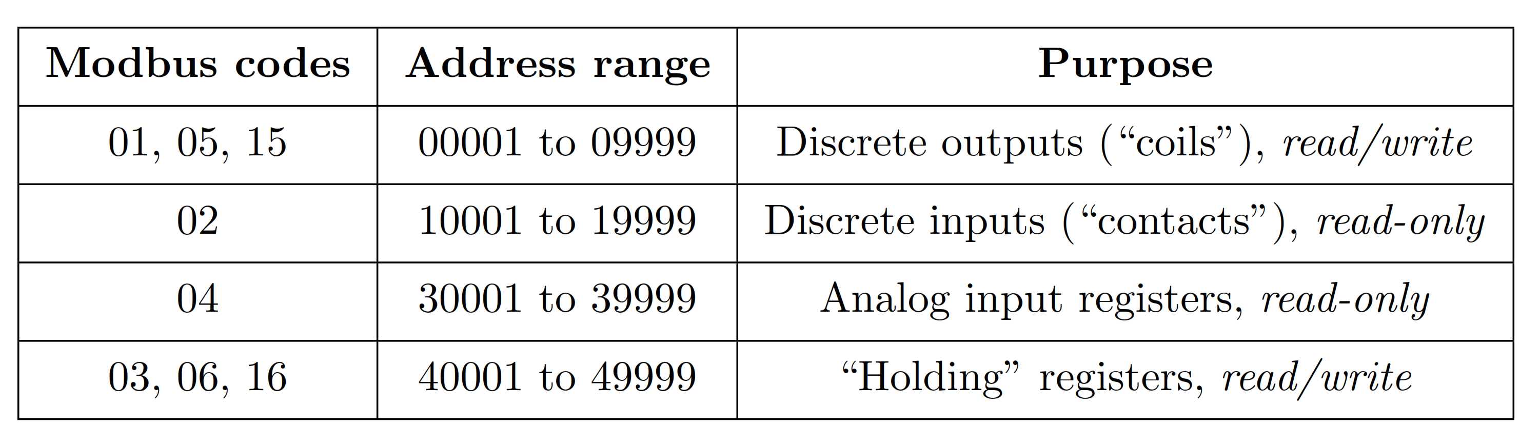
Note how all the Modbus address ranges begin at the number one, not zero as is customary for so many digital systems.
For example, a PLC with sixteen analog input channels numbered 0 through 15 by the manufacturer may “map” those input registers to Modbus addresses 30001 through 30016, respectively.
Modbus Example
While this fixed addressing scheme was correct for the original PLCs developed by Modicon, it almost never corresponds directly to the addresses within a modern Modbus master or slave device.
Manufacturers’ documentation for Modbus-compatible devices normally provides Modbus “mapping” references so technicians and engineers alike may determine which Modbus addresses refer to specific bit or word registers in the device.
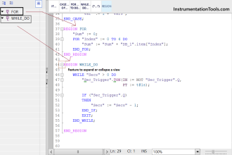
In some cases, the configuration software for a Modbus-compatible device provides a utility where you may assign specific device variables to standard Modbus register numbers.
An example of a Modbus variable mapping page appears in this screenshot taken from the configuration utility for an Emerson Smart Wireless gateway, used to “map” data from variables within WirelessHART radio-based industrial field instruments to Modbus registers within the gateway device where other devices on a wired network may read that data:
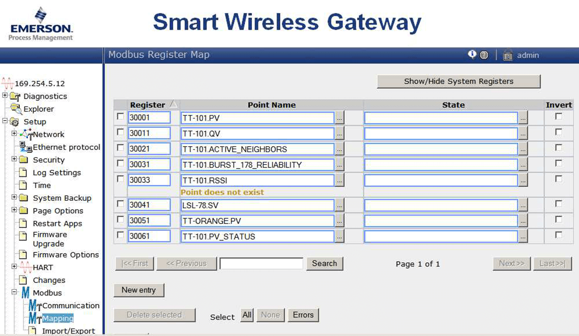
As you can see here, the primary variable within temperature sensor TT-101 (TT-101.PV) has been mapped to Modbus register 30001, where any Modbus master device on the wired network will be able to read it.
Likewise, the secondary variable within level switch LSL-78 (LSL-78.SV) has been mapped to Modbus register 30041.
It is important to note that Modbus registers are 16 bits each, which may or may not exactly fit the bit width of the device variable in question. If the device variable happens to be a 32-bit floating point number, then two contiguous Modbus registers must be used to hold that variable, only the first of which will likely appear on the Modbus mapping page (i.e. the Modbus map will only show the first Modbus register of that pair).
If the device variable happens to be a boolean (single bit), then it is likely only one bit within the 16-bit Modbus register will be used, the other 15 bits being “wasted” (unavailable) for other purposes.
Details such as this may be documented in the manual for the device performing the Modbus mapping (in this case the Emerson Smart Wireless Gateway), or you may be forced to discover them by experimentation.
© 2019-2021 by Tony R. Kuphaldt – under the terms and conditions of the Creative Commons Attribution 4.0 International Public License