Inst ToolsInst ToolsInst Tools
  • Courses
  • Automation
    • PLC
    • Control System
    • Safety System
    • Communication
    • Fire & Gas System
  • Instrumentation
    • Design
    • Pressure
    • Temperature
    • Flow
    • Level
    • Vibration
    • Analyzer
    • Control Valve
    • Switch
    • Calibration
    • Erection & Commissioning
  • Interview
    • Instrumentation
    • Electrical
    • Electronics
    • Practical
  • Q&A
    • Instrumentation
    • Control System
    • Electrical
    • Electronics
    • Analog Electronics
    • Digital Electronics
    • Power Electronics
    • Microprocessor
  • Request
Search
  • Books
  • Software
  • Projects
  • Process
  • Tools
  • Basics
  • Formula
  • Power Plant
  • Root Cause Analysis
  • Electrical Basics
  • Animation
  • Standards
  • 4-20 mA Course
  • Siemens PLC Course
Reading: Micro-impulse Level Transmitter Principle
Share
Font ResizerAa
Inst ToolsInst Tools
Font ResizerAa
  • Courses
  • Design
  • PLC
  • Interview
  • Control System
Search
  • Courses
  • Automation
    • PLC
    • Control System
    • Safety System
    • Communication
    • Fire & Gas System
  • Instrumentation
    • Design
    • Pressure
    • Temperature
    • Flow
    • Level
    • Vibration
    • Analyzer
    • Control Valve
    • Switch
    • Calibration
    • Erection & Commissioning
  • Interview
    • Instrumentation
    • Electrical
    • Electronics
    • Practical
  • Q&A
    • Instrumentation
    • Control System
    • Electrical
    • Electronics
    • Analog Electronics
    • Digital Electronics
    • Power Electronics
    • Microprocessor
  • Request
Follow US
All rights reserved. Reproduction in whole or in part without written permission is prohibited.
Inst Tools > Blog > Level Measurement > Micro-impulse Level Transmitter Principle

Micro-impulse Level Transmitter Principle

Last updated: December 26, 2018 4:15 pm
Editorial Staff
Level Measurement
No Comments
Share
2 Min Read
SHARE

Levelflex is a “downward-looking” time-of-flight system, which measures the distance from the probe mounting (top of silo) to the material level. An electrical pulse is launched and guided down the probe rope, which acts as a surface wave transmission line. When the surface wave meets a discontinuity in the surrounding medium, i.e. a sudden change in dielectric constant, it is partially reflected. The reflected pulse travels back up the probe to the pulse sampler where it is detected and timed.

Micro-impulse Level Transmitter Principle

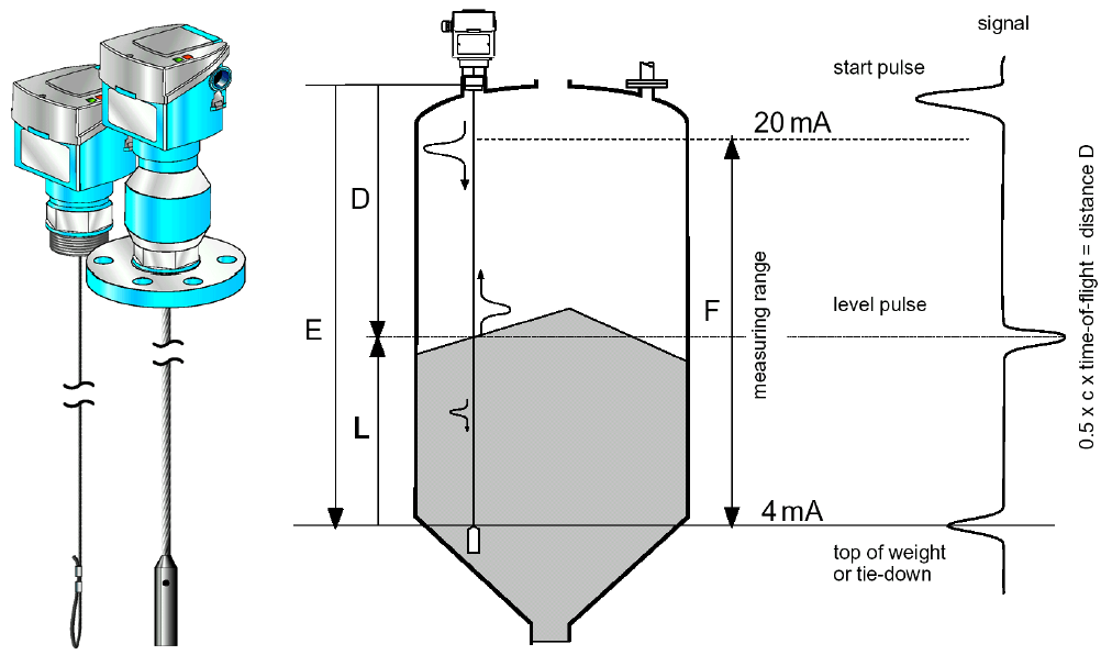
Each point along the probe is sampled for its pulse reflection behaviour. The information accumulated over the sampling cycle is captured and passed onto the signal processing, which identifies the signal produced by the change in dielectric constant at the air/product interface. The distance D to the surface of the product is proportional to the time of flight of the pulse t:

Level Transmitter Formula

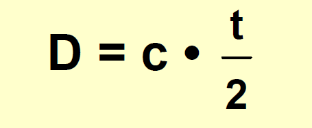
whereby c = velocity of light.

Since the empty distance E is known to the system, it is a simple matter to calculate the level L.

Level Transmitter Formula List

The top of the ballast weight or tie-down loop is zero, the span is set to 30 cm below the top thread of the process connection. For digital outputs and the display, 0% and 100% level. When hanging free, it is capable of measuring at all points from the top of the ballast weight to within 30 cm of the mounting point. The measured error is ±1%.

Depending upon application, it may be possible to measure to the end of the ballast weight or tie-down loop.

This type of meter is capable of measuring the continuous measurement of bulk solids with grain size up to 20 mm, e.g. sands, minerals, plastics, agricultural products, foodstuffs, pharmaceuticals and solid fuels. The measurement is independent of the moisture content of the bulk solid or a change in product. Silo geometry, angled material surfaces and bulk solid properties also have no effect on the measurement.

Source : N. Asyiddin

Don't Miss Our Updates
Be the first to get exclusive content straight to your email.
We promise not to spam you. You can unsubscribe at any time.
Invalid email address
You've successfully subscribed !

Continue Reading

Ultrasonic Tank Gauging
Capacitive Level Switch Principle
DP Level Measurement Problems
Magnetic Level Gauge Float Design
Capacitance Level Switch Working Principle
Difference between Transparent Level Gauge and Reflex Level Gauge
Share This Article
Facebook Whatsapp Whatsapp LinkedIn Copy Link
Share
Leave a Comment

Leave a Reply Cancel reply

Your email address will not be published. Required fields are marked *

Stay Connected

128.3kFollowersLike
69.1kFollowersFollow
210kSubscribersSubscribe
38kFollowersFollow

Categories

Explore More

Questions on Level Switches
Remote Seal Transmitters Ranging Calculation
Displacer Interface Level Measurement
Displacer Level Transmitter 5-point Calibration
DP Level Transmitter Calibration for Diaphragm Seal with Capillary
Calibration of Displacer Level Transmitter
Overview of Tank Gauging Technologies
Torque Tube Level Measurement Principle

Keep Learning

Stilling well in liquid level measurement

Stilling Well in Interface Level Measurement System

RF Level Sensors Principle

RF Level Switches Working Principle

Ultrasonic Level Measurement Questions and Answers

Ultrasonic Level Measurement Questions and Answers

RF-Capacitance Level Switch Principle

RF Capacitance Level Switch Working Principle

Open-Tank-DP-Level-Transmitter-with-Zero-Suppression-Calibration

DP Level Transmitter with Zero Suppression Calibration

Boiler-Drum-Level-transmitter-calibration

Boiler Drum Level Transmitter Calibration

Interface level Measurement

Interface Level Measurement using DP Transmitter

Magnetostrictive Level Transmitter Calibration

Magnetostrictive Level Transmitter Calibration Procedure

Learn More

Industrial Gases

Questions and Answers on Gas

Why Starting Current of Induction Motor is High

LVDT Principle

Contact Vibration Measurement

Things You Need to Know About DeviceNet

Things You Need to Know About DeviceNet

Difference Between Overcurrent and Overload

Difference Between Overcurrent and Overload

PLC Programming Classroom Bell System

Classroom Bell System – PLC Programming Practice Examples

Hot wire Anemometer Principle

Hot Wire Anemometer Principle and Types

Effect of Lead Wire Resistance on RTD

Effect of Lead Wire Resistance on RTD

Menu

  • About
  • Privacy Policy
  • Copyright

Quick Links

  • Learn PLC
  • Helping Hand
  • Part Time Job

YouTube Subscribe

Follow US
All rights reserved. Reproduction in whole or in part without written permission is prohibited.
Welcome Back!

Sign in to your account

Username or Email Address
Password

Lost your password?