The memory structure of Siemens PLC
First of all, let’s take a short look at all the types of Memories in general
- RAM: Random Access memory that is used in computers and most of the electronic devices why it’s called that? Because it’s not required to allocate a physical location of memory when performing an operation or data transitions which accelerate the process and saves time.
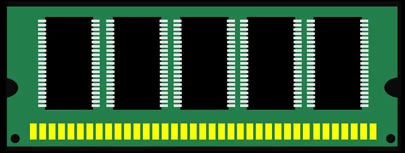
But in case of electricity cut off all the stored data in the RAM are lost.
- ROM: Read Only Memory, it’s non-volatile memory where the stored are readable but can’t be modified.
- EPROM: Erasable Read Only Memory it’s the same as ROM but the stored data can be edited, removed, and store new changes by exposing it to ultraviolet light.
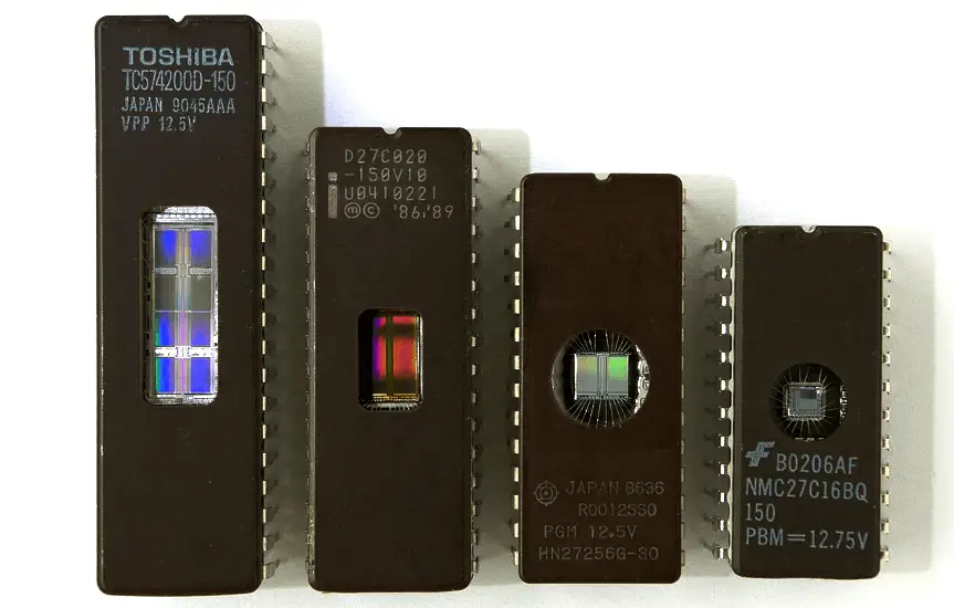
But the Way of UV exposure is a very difficult and complicated method.
- EEPROM: Electrically Erasable Programmable Read-Only Memory
It looks like the EPROM but the way of editing, removing, and store new changes for the data is done electrically not by UV light, But the number of erasing and editing it is limited by a certain number of times.
- Flash EPROM: it looks like the EEPROM but it can be erased or edited by the unlimited time of numbers.
Memory Types in Siemens PLC
In general, the S7 PLC memory is composed of 4 parts
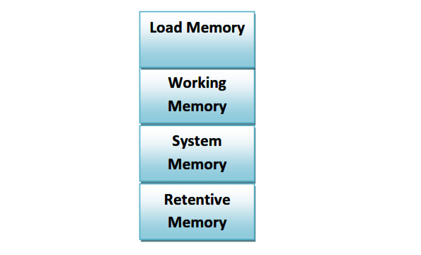
Load Memory
Stores any data downloaded from the PC to the PLC, this means that any PLC program downloaded to the PLC is stored in the Load Memory.
There are two types of Load Memory
- Internal Load Memory.
- External Load Memory.
Internal Load Memory:
it was used in the old versions of S7 PLCs in which the memory was a RAM and hence in case of power loss all the stored data in the load memory were lost, for this reason, it was mandatory to have a backup battery in order to prevent data loss.
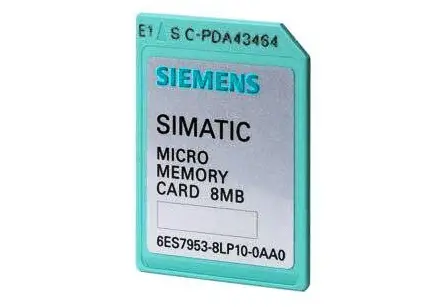
External Load Memory:
in the new versions of S7 PLCs, the load memory is external and can be purchased separately and it’s called MMC (Micro Memory Card), but in this case the CPU can’t run without the MMC installed.
Working Memory:
It’s part of memory where it can store the executive part of the PLC program, it looks like the RAM in the Computer, and in this case, the load memory is the hard disk.
System Memory:
It’s part of the memory where it can store the addressing part of the PLC program like Inputs, Outputs, Timers, Counters, and Bit memory.
Retentive Memory:
It’s part of the memory where it can store data permanently, for instance, if you want to keep the data in specific bit memory stored permanently where in the case of electricity cut off this bit memory is not impacted.
Author: Karim Ali Anwar
If you liked this article, then please subscribe to our YouTube Channel for PLC and SCADA video tutorials.
You can also follow us on Facebook and Twitter to receive daily updates.
Read Next:
- Pulse Generation in Siemens PLC
- Temperature Alarms monitor in PLC
- Upload Siemens PLC Programs
- InTouch Scada Scripting
- Programmable Logic Controller