Inst ToolsInst ToolsInst Tools
  • Courses
  • Videos
  • Q & A
    • Interview
      • Instrumentation
      • Electronics
      • Electrical
      • Practical Questions
    • MCQ
      • Instrumentation MCQ
      • Electrical MCQ
      • Electronics MCQ
      • Control Systems MCQ
      • Analog Electronics MCQ
      • Digital Electronics MCQ
      • Power Electronics MCQ
      • Microprocessor MCQ
      • Multiple Choice Questions
  • EE
    • Electronics
      • Electronics Q & A
      • Electronic Basics
      • Electronic Devices & Circuits
      • Electronics Animation
      • Digital Electronics
    • Electrical
      • Electrical Basics
      • Electrical Q & A
      • Power Electronics
      • Electrical Machines
      • Electrical Animation
      • Power Systems
      • Switchgear & Protection
      • Transmission & Distribution
  • Measure
    • Control Valves
    • Calibration
    • Temperature
    • Pressure
    • Flow
    • Level
    • Analyzers
    • Switches
    • Vibration
    • Solenoid Valve
  • Control
    • PLC Tutorials
    • Control Systems
    • Safety Instrumented System (SIS)
    • Communication
    • Fire & Gas System
  • More
    • Design
    • Tools
    • Animation
    • Basics
    • Formulas
    • Standards
    • TextBooks
    • Common
    • Software
    • Excel Tools
    • Erection & Commissioning
    • Process Fundamentals
    • Videos
    • Books
Search
All rights reserved. Reproduction in whole or in part without written permission is prohibited.
Reading: Level Measurement Lab Exercise
Share
Notification Show More
Font ResizerAa
Inst ToolsInst Tools
Font ResizerAa
  • Courses
  • PLC Tutorials
  • Control Systems
Search
  • Courses
  • Videos
  • Q & A
    • Interview
    • MCQ
  • EE
    • Electronics
    • Electrical
  • Measure
    • Control Valves
    • Calibration
    • Temperature
    • Pressure
    • Flow
    • Level
    • Analyzers
    • Switches
    • Vibration
    • Solenoid Valve
  • Control
    • PLC Tutorials
    • Control Systems
    • Safety Instrumented System (SIS)
    • Communication
    • Fire & Gas System
  • More
    • Design
    • Tools
    • Animation
    • Basics
    • Formulas
    • Standards
    • TextBooks
    • Common
    • Software
    • Excel Tools
    • Erection & Commissioning
    • Process Fundamentals
    • Videos
    • Books
Follow US
All rights reserved. Reproduction in whole or in part without written permission is prohibited.
Inst Tools > Blog > Practical Questions > Level Measurement Lab Exercise

Level Measurement Lab Exercise

In this guide you will find the operational procedure for the instrumentation level measurement lab exercise.

Last updated: January 13, 2021 8:48 pm
Editorial Staff
Practical Questions
No Comments
Share
4 Min Read
SHARE

After getting your prototype sketch approved by the instructor, you are cleared to begin building your system.

Transmitters attach to 2-inch pipes using special brackets and U-bolts. These brackets and U-bolts are located along with the transmitters in the instrument storage area.

Feel free to use 1/4 inch plastic tubing for all the pneumatic signal connections, and be sure not to exceed the rated supply pressure (as documented in the transmitter’s manual).

Finally, your level-measurement system needs to have a loop number, so all instruments may be properly labeled. This loop number needs to be unique, so that another team does not label their instruments and tubes the same as yours.

One way to make your loop number unique is to use the equivalent resistor color code value for your team’s color in the loop number. For example, if you are on the “Red” team, your loop number could be “2”.

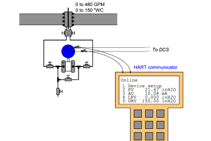
It is recommended that you use a different electronic indicator or indicating controller as the display unit on this lab exercise, to give yourself wider exposure to the controller/indicator options in our lab facility.

For example, if in the previous lab exercise your team used a panel-mount electronic indicating controller, consider using a PLC or a DCS as the electronic indicator in this lab exercise.

Common Mistakes

Neglecting to consult the manufacturer’s documentation for field instruments (e.g. how to connect pneumatic signal lines, how to calibrate them).

Mounting the field instrument(s) in awkward positions, making it difficult to reach tube connectors or to remove covers when installed.

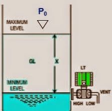
Mounting the transmitter above the LRV point, rather than below (to avoid loss of impulse line liquid fill when the vessel’s level is drained to the LRV point).

Improper pipe/tube fitting installation (e.g. trying to thread tube fittings into pipe fittings and vice-versa).

Applying Teflon tape to tube fitting threads; failing to apply Teflon tape to pipe fitting threads.

Over-tightening tube fittings (remember, no more than 1-1/4 turns when installing a new ferrule set, and no more than “snug” when re-making the connection!).

Students working on portions of the system in isolation, not sharing with their teammates what they did and how. It is important that the whole team learns all aspects of their system!

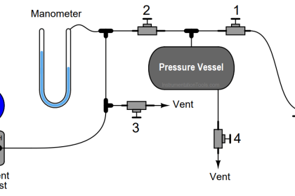
It is relatively easy to construct a “process vessel” for measuring water level in, by using inexpensive PVC plastic piping and fittings:

Process vessel for measuring water level

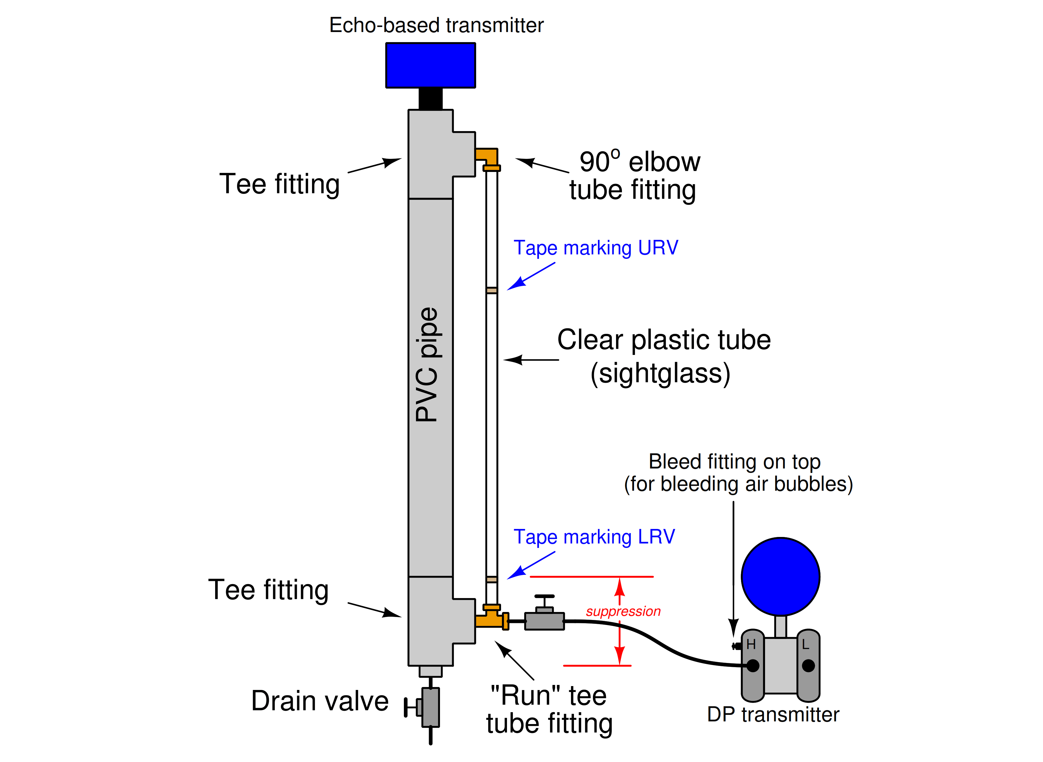
Water is poured in the top, through the open tee fitting, and is drained through a valve at the bottom (preferably a 1/4 turn ball valve).

Even with an instrument valve manifold on the ∆P transmitter, a shutoff valve is advisable between the process vessel connection and the transmitter to facilitate the removal of the transmitter and manifold without having to drain the vessel.

Note how the DP transmitter is mounted lower than the LRV mark on the sight-glass: this is intentional, as it maintains a liquid fill throughout the impulse line even when the vessel is at its lowest liquid level.

If the transmitter is mounted above this point, the possibility exists for that liquid fill to dribble out of the impulse line if ever the vessel’s level goes too low, and this loss of liquid fill will cause calibration errors!

Building a functioning system should take no more than one full lab session (3 hours) if all components are readily available and the team is working efficiently!

Read Next:

  • Loop diagram Lab Exercise
  • Remote Seal Pressure Transmitter
  • Tube and tube fittings
  • Instrument Tube Bending

Credits: Tony R. Kuphaldt

Don't Miss Our Updates
Be the first to get exclusive content straight to your email.
We promise not to spam you. You can unsubscribe at any time.
Invalid email address
You've successfully subscribed !

Recommended Articles

Practical Process Control System Questions & Answers – 1
PLC Electric Motor Interlocks
Troubleshoot Allen Bradley PLC Logic
PLC Switch Actuation Status
Questions on DP Transmitter Wet Leg Compensating Impulse Line
Calculate the Thermocouple’s Measurement Junction Temperature
Share This Article
Facebook Whatsapp Whatsapp LinkedIn Copy Link
Share
Leave a Comment

Leave a Reply Cancel reply

Your email address will not be published. Required fields are marked *

Stay Connected

128.3kFollowersLike
69.1kFollowersFollow
208kSubscribersSubscribe
38kFollowersFollow

Categories

Recent Comments

  • William Snyder on Top Non-PLC Certification Courses for Automation Professionals
  • Kamli on Top Free PLC Software
  • Guifty Shimica on Top Non-PLC Certification Courses for Automation Professionals
  • Guifty Shimica on Top Non-PLC Certification Courses for Automation Professionals

Related Articles

Problem on Weigh feeder

Problem on Weigh feeder

solenoid valves trip

Identify Solenoid Valves Energized or de-energized?

Foxboro pneumatic instruments

Pneumatic Force Balance Instrument

Determine the Pressure at Each Port of DP Transmitter

Determine the Pressure at Each Port of DP Transmitter

Which instrument is faulty

Which Instrument is Faulty? Transmitter, Recorder, or Controller

AB PLC Temperature Switch

Programmable Logic Controller (PLC) Questions and Answers – 17

Calculate Hydraulic Pressure of a Drum

Calculate Hydraulic Pressure of a Process Vessel

Which instrument is at fault in this system

Which Instrument is at Fault in this System?

More Articles

Digital Electronics Multiple Choice Questions

Ring Counter Objective Questions

Effect of Lead Wire Resistance on RTD

Effect of Lead Wire Resistance on RTD

Voltmeter Calibration

Calibration Procedure of Voltmeter and Ammeter

Tank uses 3 Pressure Transmitters to Measure Level & Density

Tank uses 3 Pressure Transmitters to Measure Level & Density

PLC Program for Water Level Control

PLC Program for Water Level Control Logic

Scaling in PLC

PLC Ladder Logic for Sensor Scaling with Offset

Electron Gun of CRT

Electron Gun of Cathode Ray Tube

High-Speed Inputs in PLC

What are High-Speed Inputs in PLC?

Follow US
All rights reserved. Reproduction in whole or in part without written permission is prohibited.
Welcome Back!

Sign in to your account

Username or Email Address
Password

Lost your password?