Inst ToolsInst ToolsInst Tools
  • Courses
  • Automation
    • PLC
    • Control System
    • Safety System
    • Communication
    • Fire & Gas System
  • Instrumentation
    • Design
    • Pressure
    • Temperature
    • Flow
    • Level
    • Vibration
    • Analyzer
    • Control Valve
    • Switch
    • Calibration
    • Erection & Commissioning
  • Interview
    • Instrumentation
    • Electrical
    • Electronics
    • Practical
  • Q&A
    • Instrumentation
    • Control System
    • Electrical
    • Electronics
    • Analog Electronics
    • Digital Electronics
    • Power Electronics
    • Microprocessor
  • Request
Search
  • Books
  • Software
  • Projects
  • Process
  • Tools
  • Basics
  • Formula
  • Power Plant
  • Root Cause Analysis
  • Electrical Basics
  • Animation
  • Standards
  • 4-20 mA Course
  • Siemens PLC Course
Reading: Laws of Boolean Algebra using Ladder Logic
Share
Notification Show More
Font ResizerAa
Inst ToolsInst Tools
Font ResizerAa
  • Courses
  • Design
  • PLC
  • Interview
  • Control System
Search
  • Courses
  • Automation
    • PLC
    • Control System
    • Safety System
    • Communication
    • Fire & Gas System
  • Instrumentation
    • Design
    • Pressure
    • Temperature
    • Flow
    • Level
    • Vibration
    • Analyzer
    • Control Valve
    • Switch
    • Calibration
    • Erection & Commissioning
  • Interview
    • Instrumentation
    • Electrical
    • Electronics
    • Practical
  • Q&A
    • Instrumentation
    • Control System
    • Electrical
    • Electronics
    • Analog Electronics
    • Digital Electronics
    • Power Electronics
    • Microprocessor
  • Request
Follow US
All rights reserved. Reproduction in whole or in part without written permission is prohibited.
Inst Tools > Blog > PLC Tutorials > Laws of Boolean Algebra using Ladder Logic

Laws of Boolean Algebra using Ladder Logic

Last updated: March 4, 2021 3:47 pm
Editorial Staff
PLC Tutorials
No Comments
Share
3 Min Read
SHARE

Laws of Boolean algebra are used in digital electronics. Explain the Boolean algebra law using ladder language.

Contents
Laws of Boolean Algebra using Ladder LogicPLC Ladder programming explanation

Laws of Boolean Algebra using Ladder Logic

Laws of Boolean Algebra using Ladder Logic
There are three basic laws of Boolean algebra.
  • Commutative law,
  • associate laws and
  • distributive laws.

The commutative laws and associate laws are used for addition and multiplications and distributive laws are used for gate logic implementation.

Here take tree variable for this explanation for these laws. A, B and C are the variables for the explanation.

The commutative law of addition of two variables is AB=BA.

The associate law of addition for three variables is written as A+ (B+C) = (A+B) +C.

The distributive law is written for three variables as A (B+C) =AB+AC.

List of Inputs/Outputs

List of Inputs

  • I1 :- A
  • I2 :- B
  • I3 : -C

List of Outputs

  • Q1 :- Output 1
  • Q2 :- Output 2
  • Q3 :- Output 3
  • Q4 :- Output 4

Memory coil

  • M2 :- for Commutative laws
  • M3 :- for associate law
  • M4 :- for distributive law

PLC Ladder programming explanation

NETWORK 1 :-

Here OR gate is used for inputs A and B. Result will be stored in M2 memory.
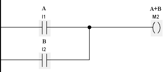
OR Gate using Ladder Logic

NETWORK 2 :-

Here combinational logic is used for commutative laws. Final result will be Q1.
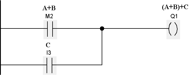
commutative Law Ladder Logic

NETWORK 3 :-

Here AND gate is used for inputs A and B. Result will be stored in M1 coil.

AND Gate Ladder Diagram

NETWORK 4 :-

Combinational logic is used for associate law. Final result will be Q2

Associate Law Ladder Logic

NETWORK 5 :-

Ladder Logic AND Gate Function

AND gate of two inputs (A&B) for distributive law. Result will be stored in M3.

NETWORK 6 :-

AND gate of two inputs (A&C) for distributive law. Result will be stored in M4.

Distributive Law Ladder Logic

NETWORK 7 :-

OR gate of M3 and M4. Result will be stored in Q3.
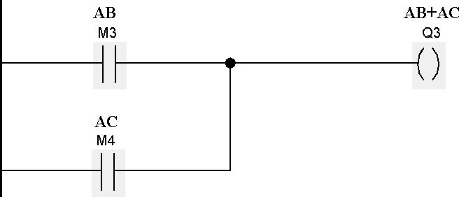
OR gate function ladder diagram

NETWORK 8 :-

Other combination of distributive law.
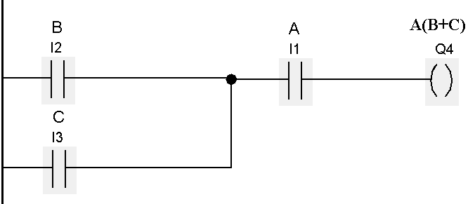
Boolean Algebra Ladder Diagram

Note:-Above application may be different from actual application. This example is only for explanation and educational purpose only. We can implement this logic in other PLC also. This is the simple concept for Laws of Boolean algebra using ladder logic, we can use this concept in other examples also.

All parameters and graphical representations considered in this example are for explanation purpose only, parameters or representation may be different in actual applications. Also all interlocks are not considered in the application.

Author : Bhavesh

If you liked this article, then please subscribe to our YouTube Channel for PLC and SCADA video tutorials.

You can also follow us on Facebook and Twitter to receive daily updates.

Read Next:

Boolean Algebraic Identities

Ladder Diagram Programming

PLC Input Output Modules

Introduction to Karnaugh Mapping

What is Kirchhoff’s Current Law
Don't Miss Our Updates
Be the first to get exclusive content straight to your email.
We promise not to spam you. You can unsubscribe at any time.
Invalid email address
You've successfully subscribed !

Continue Reading

Relay circuits
PLC Analog Input Sampling Ladder Logic
FIFO Instruction in Allen Bradley PLC Programming
Delta HMI and VFD Control with Modbus
PLC Logic Example on Multiple Switches and Motors
PLC Program for Controlling a Water Pump with 3 Power Sources
Share This Article
Facebook Whatsapp Whatsapp LinkedIn Copy Link
Share
Leave a Comment

Leave a Reply Cancel reply

Your email address will not be published. Required fields are marked *

Stay Connected

128.3kFollowersLike
69.1kFollowersFollow
210kSubscribersSubscribe
38kFollowersFollow

Categories

Explore More

PLC to PLC Communication using S7 Connection PUT & GET Instructions
Troubleshooting a 4-20mA Current loop
Features of Scada Which are Must in an IoT System
PLC Programming for Tank Heating Control using Heater
What are AI, AO, DI, and DO? – Definition, Examples, Purpose
UPS Working Principle and Types – Offline and Online UPS Systems
PLC Ladder Logic for Opposite Acting Control Valves Application
How to use Master Control Reset (MCR) Instruction in PLC

Keep Learning

Comparison of Proportional Integral Derivative Controllers (PID)

Comparison of Proportional Integral Derivative Controllers (PID)

PLC Programming for Sequential Batch Mixing System

PLC Programming for Sequential Batch Mixing System

PLC Programmer Unknown Do's

Unknown Do’s Need to Know as a PLC Programmer

Communication Protocols in PLC

Various Communication Protocols in PLC

PLC FBD Example for Tank Liquid Heating Control by Steam Flow

PLC FBD Example for Tank Liquid Heating Control by Steam Flow

Examples of PLC Programming using Boolean Functions

Examples of PLC Programming using Boolean Functions

Structured Text PLC Program for Sequential Process Data Storage

Structured Text PLC Code for Sequential Process Data Storage

PLC Program Upload

How to Upload Siemens PLC Programs?

Learn More

Electronic Devices & Circuits Objective Questions

Electronic Devices & Circuits Quiz – Set 10

What is Data Acquisition

What is Data Acquisition? – Elements and Components

Choked Flow of Control Valve

Choked Flow of Control Valves

Temperature Switch

Temperature Switch Working Principle

shape of the trim determines the valve characteristic

Control Valve Characteristics

Current to Pressure Converter Principle

Current to Pressure (I/P) Converter Principle

Solenoid Valve Terminology

Solenoid Valves Terminology

Power Electronics Objective Questions

Thyristor Mounting Objective Questions and Answers

Menu

  • About
  • Privacy Policy
  • Copyright

Quick Links

  • Learn PLC
  • Helping Hand
  • Part Time Job

YouTube Subscribe

Follow US
All rights reserved. Reproduction in whole or in part without written permission is prohibited.
Welcome Back!

Sign in to your account

Username or Email Address
Password

Lost your password?