Inst ToolsInst ToolsInst Tools
  • Courses
  • Automation
    • PLC
    • Control System
    • Safety System
    • Communication
    • Fire & Gas System
  • Instrumentation
    • Design
    • Pressure
    • Temperature
    • Flow
    • Level
    • Vibration
    • Analyzer
    • Control Valve
    • Switch
    • Calibration
    • Erection & Commissioning
  • Interview
    • Instrumentation
    • Electrical
    • Electronics
    • Practical
  • Q&A
    • Instrumentation
    • Control System
    • Electrical
    • Electronics
    • Analog Electronics
    • Digital Electronics
    • Power Electronics
    • Microprocessor
  • Request
Search
  • Books
  • Software
  • Projects
  • Process
  • Tools
  • Basics
  • Formula
  • Power Plant
  • Root Cause Analysis
  • Electrical Basics
  • Animation
  • Standards
  • 4-20 mA Course
  • Siemens PLC Course
Reading: Jog Function in Motor Start Stop Logic using PLC
Share
Font ResizerAa
Inst ToolsInst Tools
Font ResizerAa
  • Courses
  • Design
  • PLC
  • Interview
  • Control System
Search
  • Courses
  • Automation
    • PLC
    • Control System
    • Safety System
    • Communication
    • Fire & Gas System
  • Instrumentation
    • Design
    • Pressure
    • Temperature
    • Flow
    • Level
    • Vibration
    • Analyzer
    • Control Valve
    • Switch
    • Calibration
    • Erection & Commissioning
  • Interview
    • Instrumentation
    • Electrical
    • Electronics
    • Practical
  • Q&A
    • Instrumentation
    • Control System
    • Electrical
    • Electronics
    • Analog Electronics
    • Digital Electronics
    • Power Electronics
    • Microprocessor
  • Request
Follow US
All rights reserved. Reproduction in whole or in part without written permission is prohibited.
Inst Tools > Blog > PLC Tutorials > Jog Function in Motor Start Stop Logic using PLC

Jog Function in Motor Start Stop Logic using PLC

Last updated: March 4, 2021 3:44 pm
Editorial Staff
PLC Tutorials
No Comments
Share
3 Min Read
SHARE

The common usage of the word ‘Jogging’ in our daily life is for slow running. ‘Jogging’ or ‘inching’ of a motor also implies the same i.e ., to have small movements of the driven machine . In jogging, starting and stopping of a motor is under the direct control of the operator .

Jogging is also defined as the brief closure of a motor circuit to energize a motor for a short period of time and perform a small movement of driven machine. Motor Start/Stop Circuit with Jog switch Designed to turn an output on and off that can in turn be wired to a motor starter to start/stop a motor

Sometimes in motor logic we need to bypass start button and latching logic for testing purpose or to run the motor momentarily. A motor is jogged for the following reasons: to align and space machine parts; to position a tool accurately; to thread cloth, paper, or sheet steel; and to provide small controlled movement.

Generally in motor logic there are two push buttons are used start push button and stop push button (START PB and STOP PB). As per electrical wiring we need to insert START PB after STOP PB and jog button is also inserted in series with STOP button. Generally two contacts are used in this button (NO and NC contacts).

List of Inputs

  • Start PB :- I1
  • Stop PB :- I2
  • Jog PB :- I3

List of Outputs

  • Motor :- Q1

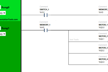
PLC Ladder Logic for Motor Jog Function

  • In this logic we have used START/STOP logic of motor and jog function.
  • In this network we have connected START PB in series with STOP PB.
  • Also we have connected NC contact of jog PB in series with latching contact of motor, so it will allow logic to pass in normal condition.
Jog function in Motor Start Stop Logic using PLC

Author : Bhavesh

If you liked this article, then please subscribe to our YouTube Channel for PLC and SCADA video tutorials.

You can also follow us on Facebook and Twitter to receive daily updates.

Read Next:

Relay Latching Circuit using Button

Programmable Logic Controller Quiz

Grinding Machine PLC Program

PLC Project for a School

Elevator Ladder Logic Porject

Don't Miss Our Updates
Be the first to get exclusive content straight to your email.
We promise not to spam you. You can unsubscribe at any time.
Invalid email address
You've successfully subscribed !

Continue Reading

Types of Limit Switches – Principle, Advantages, Disadvantages
Free Siemens PLC Training Course
4-20mA Loop Power Supply Questions and Answers
PLC Timer Programming Examples – TON, TOF, TP and TONR
Tia Portal – Optimized and Standard Data Block Access
Cybersecurity in PLC
Share This Article
Facebook Whatsapp Whatsapp LinkedIn Copy Link
Share
Leave a Comment

Leave a Reply Cancel reply

Your email address will not be published. Required fields are marked *

Stay Connected

128.3kFollowersLike
69.1kFollowersFollow
210kSubscribersSubscribe
38kFollowersFollow

Categories

Explore More

How to Work with Delta PLC Simulator?
How to Program a Star-Delta System using 1 Button in PLC?
PLC vs PAC – Understanding the Key Differences and Similarities
PLC Digital Signals Wiring Techniques
How to Use Analog Input in Mitsubishi FX3U LOLLETTE PLC?
Overview of Industrial Control Systems
What is an RTU? – Remote Terminal Unit
If Else Statement in SCL Language

Keep Learning

How to Update the Firmware Version of your PLC

How to Update the Firmware Version of your PLC? – TIA Portal

PLC Program

Example PLC Program

PLC Program to Energize & De-energize the Outputs based on Events

PLC Energize or De-energize the Outputs based on Events

Structured Text Automatic Gate Logic

Structured Text PLC Programming for Automatic Gate Control

Configure Analog Inputs and Outputs in Delta PLC

How to Configure Analog Inputs and Outputs in Delta PLC?

What is a Tag in SCADA

What is a Tag? Types of Tags in SCADA

Simatic Prosave HMI

How to Backup and Restore from Simatic Prosave HMI?

V1000 Family Programming Simulator Tool

VFD Simulator Download – Free Yaskawa V1000 Software

Learn More

Electrical Machines Objective Questions

Electrical Machines MCQ Series 17

Field Instruments

Is Vacuum affects Field Instruments in Industries?

Communication between Intouch Scada and Allen Bradley PLC

Communication between InTouch Scada and Allen Bradley PLC

Calibration Sheet

Calibration : Up-tests and Down-tests

CIPP Lining Procedure

What is CIPP Lining? Procedure and Advantages

Drum Level Compensation of DP Transmitter

Drum Level Compensation and Range Calculation of DP Transmitter

Proportional Control Theory

Proportional-only Offset

Difference between PLC and Computers

Difference between PLC and Computers

Menu

  • About
  • Privacy Policy
  • Copyright

Quick Links

  • Learn PLC
  • Helping Hand
  • Part Time Job

YouTube Subscribe

Follow US
All rights reserved. Reproduction in whole or in part without written permission is prohibited.
Welcome Back!

Sign in to your account

Username or Email Address
Password

Lost your password?