This article is about communication between InTouch SCADA and Allen Bradley PLC with a ladder logic example with screenshots.
Do follow the below steps for establishing the communication process.
Open RSlogix software along with RSlinx and emulator.
Create a new project in RSlogix and established communication with an emulator.
Open InTouch SCADA software.
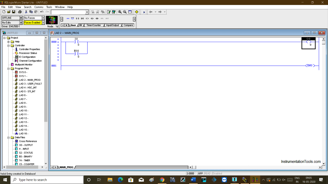
As you can see in the below window of RSlogix I have created a small example with one input and output.
In branch, I have use memory bit which we will use in SCADA to give a command.
Now, let open RSlinx. Click on option “DDE/OPC” and choose “topic configuration”.
Following window will pop-up. Choose “New” to proceed.
Create a new topic as I have created communication and choose communication protocol. Click “apply” then “done” to proceed.
Now open InTouch SCADA. Create a new project.
As we have used one input and output we have to create one input button and output button as shown in the below window.
Hit double click on a button will open up the following window. Choose “Discrete” will open up a new window.
Give a name to button and hit “ok” to proceed.
Choose I/O Discrete in the “Type” option. Then click on “access name”.
Write a bit address in “item” for input which we have used in the programming software (check step no. 4).
Clicking on Access name will open another window. Click on “add” as shown in the below window.
This is a very important step to establish communication.
Access: Give any name
Application name: RSlogix
Topic name: communication (the same name we have used in step no. 7)
Choose “DDE” as a communication protocol and hit “ok” to proceed.
After configuration hit “save” and close the pop-up.
For output, we have select “fill color” property and choose “Discrete”.
Do follow the same procedure for output as shown in the below window.
Communication has established. Test the logic. Keep a window in “runtime” and put CPU in “run” mode.
As you can see in the below window output gets energized if I give the command from SCADA.
Author: Suhel Patel
If you liked this article, then please subscribe to our YouTube Channel for PLC and SCADA video tutorials.
You can also follow us on Facebook and Twitter to receive daily updates.
Read Next:
Learn an example PLC program to control a pump based on level sensors using ladder…
In the PLC timer application for security camera recording, when motion is detected then camera…
In this example, we will learn batch mixing with PLC ladder logic program using timer…
This PLC example on manufacturing line assembly is an intermediate-level PLC program prepared for the…
In this article, you will learn the PLC programming example with pushbutton and motor control…
This article teaches how to convert Boolean logic to PLC programming ladder logic with the…


View Comments
is intouch scada free version is available?
Yes, available
Can I communicate using RSLinx classic lite or gateway is must