Inst ToolsInst ToolsInst Tools
  • Courses
  • Automation
    • PLC
    • Control System
    • Safety System
    • Communication
    • Fire & Gas System
  • Instrumentation
    • Design
    • Pressure
    • Temperature
    • Flow
    • Level
    • Vibration
    • Analyzer
    • Control Valve
    • Switch
    • Calibration
    • Erection & Commissioning
  • Interview
    • Instrumentation
    • Electrical
    • Electronics
    • Practical
  • Q&A
    • Instrumentation
    • Control System
    • Electrical
    • Electronics
    • Analog Electronics
    • Digital Electronics
    • Power Electronics
    • Microprocessor
  • Request
Search
  • Books
  • Software
  • Projects
  • Process
  • Tools
  • Basics
  • Formula
  • Power Plant
  • Root Cause Analysis
  • Electrical Basics
  • Animation
  • Standards
  • 4-20 mA Course
  • Siemens PLC Course
Reading: Interposing Relay Panel (IRP) – Wiring and Testing Requirements
Share
Font ResizerAa
Inst ToolsInst Tools
Font ResizerAa
  • Courses
  • Design
  • PLC
  • Interview
  • Control System
Search
  • Courses
  • Automation
    • PLC
    • Control System
    • Safety System
    • Communication
    • Fire & Gas System
  • Instrumentation
    • Design
    • Pressure
    • Temperature
    • Flow
    • Level
    • Vibration
    • Analyzer
    • Control Valve
    • Switch
    • Calibration
    • Erection & Commissioning
  • Interview
    • Instrumentation
    • Electrical
    • Electronics
    • Practical
  • Q&A
    • Instrumentation
    • Control System
    • Electrical
    • Electronics
    • Analog Electronics
    • Digital Electronics
    • Power Electronics
    • Microprocessor
  • Request
Follow US
All rights reserved. Reproduction in whole or in part without written permission is prohibited.
Inst Tools > Blog > PLC Tutorials > Interposing Relay Panel (IRP) – Wiring and Testing Requirements

Interposing Relay Panel (IRP) – Wiring and Testing Requirements

The components location, wiring, and termination in the Interposing Relay Panel (IRP) shall be as per the approved system drawing.

Last updated: March 4, 2021 10:53 am
Editorial Staff
PLC Tutorials Control Systems
1 Comment
Share
3 Min Read
SHARE

Interposing Relay Panel (IRP)

Interposing Relay Panel (IRP)

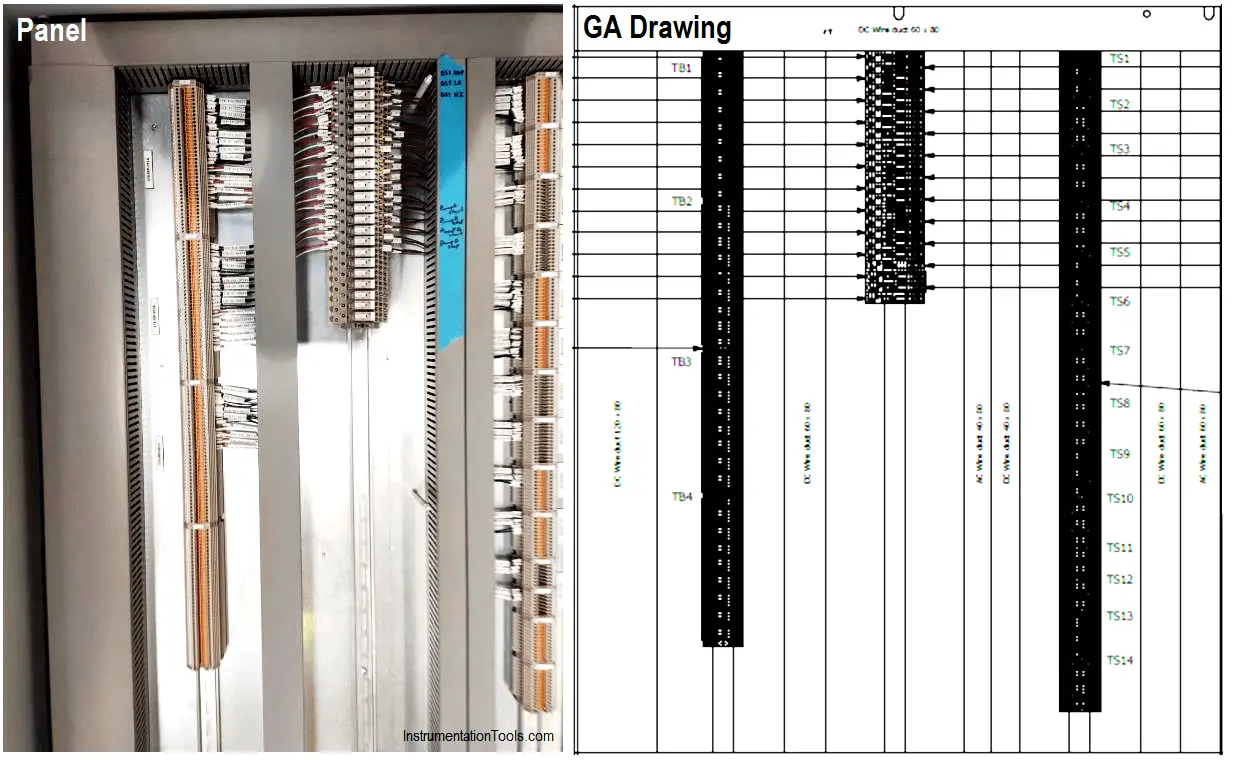
Check the locations of the components like relay’s and Terminal blocks in the IRP panel shall be as per the approved IRP GA/IA drawing. Refer to the above photograph for easy understanding.

Contents
Interposing Relay Panel (IRP)Termination of Digital Input (DI) signalsTesting of the Digital input (DI) SignalsTermination of Digital Output (DO) SignalsTesting of Digital Output (DO) Signals

Also Read: What Is Interposing Relay in a PLC?

Termination of Digital Input (DI) signals

  • Identify the terminal block for the DI signal as per Instrument wiring interconnection drawing and Electrical schematic wiring drawing.
  • Check the cross-wiring between the Electrical side MCC terminal and the System side Instrument terminal.
  • Check the proper ferrule for the input signal i.e. Status, L/R, and Fault from and to assigned terminals.

Testing of the Digital input (DI) Signals

  • Identify the terminal block for the DI signal as per Instrument wiring interconnection drawing and Electrical schematic wiring drawing.
  • Short the terminal blocks of the DI signal at the MCC end in the IRP cabinet.
  • Check and ensure the continuity in the multimeter at the terminal end in the IRP cabinet for the same.
  • Repeat the above steps for each DI signal and highlight each signal in the I/O list to ensure all the DI signals are covered under the test.

Termination of Digital Output (DO) Signals

  • Identify the terminal block and relay numbering for the DO signal as per Instrument wiring interconnection drawing and Electrical schematic wiring drawing.
  • Check the cross-wiring between the Electrical side MCC terminal, Relay, and the System side Instrument terminal.
  • Check the proper ferrule for the output signal i.e. Start, Stop, and Trip from and to assigned terminals.

Testing of Digital Output (DO) Signals

  • Identify the terminal block and relay numbering for the DO signal as per Instrument wiring interconnection drawing and Electrical schematic wiring drawing.
  • Inject 24V DC with current ranging from (50-100mA) to the Coil side of the DO signal.
  • Confirm that the intended relay is energized / de-energized as per the Electrical schematic wiring drawing.
  • Check and ensure the continuity at the MCC end for the same signal using a multimeter.
  • Repeat the above steps for each DO signal and highlight each signal in the I/O list to ensure all the DO signals are covered under the test.

Note: Hope the above explanation for the wiring and testing of the Interposing relay panel is understood.

Have a nice day!!

Stay Safe!!

Author: Mohammed Khaleel

If you liked this article, then please subscribe to our YouTube Channel for PLC and SCADA video tutorials.

You can also follow us on Facebook and Twitter to receive daily updates.

Read Next:

  • Loop Test Requirements
  • Digital Signals Wiring
  • Yokogawa DCS System
  • Loop diagram Lab Exercise
  • Flow Control Loop
Don't Miss Our Updates
Be the first to get exclusive content straight to your email.
We promise not to spam you. You can unsubscribe at any time.
Invalid email address
You've successfully subscribed !

Continue Reading

Components of PLC
Basic Pumping System Application Used in Industrial Automation
Series Tanks Level Control using PLC Ladder Programming
Inside the PLC Control Panel: How Much Do You Know?
How to Reduce Relay Noise in PLC Systems?
What are FIFO and LIFO Sequences in PLC?
Share This Article
Facebook Whatsapp Whatsapp LinkedIn Copy Link
Share
1 Comment
  • Suresh vittamsetty says:
    September 21, 2020 at 10:22 pm

    Please can you explain freewheeling diode for inductance

    Reply

Leave a Reply Cancel reply

Your email address will not be published. Required fields are marked *

Stay Connected

128.3kFollowersLike
69.1kFollowersFollow
210kSubscribersSubscribe
38kFollowersFollow

Categories

Explore More

Conveyor Sorting Machine PLC Program with Calculation Function
What is Alarm Shelving? – Nuisance Alarms, Types, Suppression
Building Management System
Case Statement in SCL Language
What is PID Controller?
Difference between Compact PLC and Modular PLC
PLC Analog Input Conversion Formula
MODBUS ASCII Communication Protocol Explained

Keep Learning

Use of Regions in SCL Language

Use of Regions in SCL Language

How to do Force in GE PLC Proficy Machine Edition?

On Delay Timer using PLC

ON Delay Timer using PLC

Automatic Car Washing Process using PLC Ladder Diagram

Automatic Car Washing using PLC

PLC-Complete-Training-Package

Free PLC Training Software Download

Create an Application in HMI using Tia Portal

Create an Application in HMI using Tia Portal

Boiler Intelligent Control Cabinet

IoT based Smart Boiler Control System with Cloud PLC and SCADA

Function Block Diagram - Studio 5000 Logix Designer

Define the Order of Execution in Functional Block Diagram of Studio 5000

Learn More

Rotameters Working

Rotameter Working Principle and Animation

HVAC Principle and Theory

Recommendations to HVAC Engineers

Proportional only Control Theory

Proportional-only Control Theory

Batteries in parallel animation

Batteries in Series and Parallel Animation

6.6kV HV Induction motor Protection

Electrical Ground Loop

How to Solve Electrical Ground Loop Problems?

How to Test a Pressure Gauge

How to Test a Pressure Gauge

Pressure Control Loop

Pressure Control Loop Wiring Connections

Menu

  • About
  • Privacy Policy
  • Copyright

Quick Links

  • Learn PLC
  • Helping Hand
  • Part Time Job

YouTube Subscribe

Follow US
All rights reserved. Reproduction in whole or in part without written permission is prohibited.
Welcome Back!

Sign in to your account

Username or Email Address
Password

Lost your password?