Inst ToolsInst ToolsInst Tools
  • Courses
  • Automation
    • PLC
    • Control System
    • Safety System
    • Communication
    • Fire & Gas System
  • Instrumentation
    • Design
    • Pressure
    • Temperature
    • Flow
    • Level
    • Vibration
    • Analyzer
    • Control Valve
    • Switch
    • Calibration
    • Erection & Commissioning
  • Interview
    • Instrumentation
    • Electrical
    • Electronics
    • Practical
  • Q&A
    • Instrumentation
    • Control System
    • Electrical
    • Electronics
    • Analog Electronics
    • Digital Electronics
    • Power Electronics
    • Microprocessor
  • Request
Search
  • Books
  • Software
  • Projects
  • Process
  • Tools
  • Basics
  • Formula
  • Power Plant
  • Root Cause Analysis
  • Electrical Basics
  • Animation
  • Standards
  • 4-20 mA Course
  • Siemens PLC Course
Reading: Interferometer Principle
Share
Font ResizerAa
Inst ToolsInst Tools
Font ResizerAa
  • Courses
  • Design
  • PLC
  • Interview
  • Control System
Search
  • Courses
  • Automation
    • PLC
    • Control System
    • Safety System
    • Communication
    • Fire & Gas System
  • Instrumentation
    • Design
    • Pressure
    • Temperature
    • Flow
    • Level
    • Vibration
    • Analyzer
    • Control Valve
    • Switch
    • Calibration
    • Erection & Commissioning
  • Interview
    • Instrumentation
    • Electrical
    • Electronics
    • Practical
  • Q&A
    • Instrumentation
    • Control System
    • Electrical
    • Electronics
    • Analog Electronics
    • Digital Electronics
    • Power Electronics
    • Microprocessor
  • Request
Follow US
All rights reserved. Reproduction in whole or in part without written permission is prohibited.
Inst Tools > Blog > Flow Measurement > Interferometer Principle

Interferometer Principle

The variation of refractive index of flowing gas with density is basic principle used in Interferometer. Interference of light waves is used for measurement

Last updated: November 2, 2023 9:36 am
Editorial Staff
Flow Measurement
No Comments
Share
4 Min Read
SHARE

An interferometer is a precise instrument for flow visualization. The variation of the refractive index of the flowing gas with density is the basic principle used in this system.

Contents
InterferometerOperation of Interferometer

The principle of interference of light waves is used. At a phase angle, the number of fringes is in relation to the change in density with respect to the zero fringe condition.

Interferometer
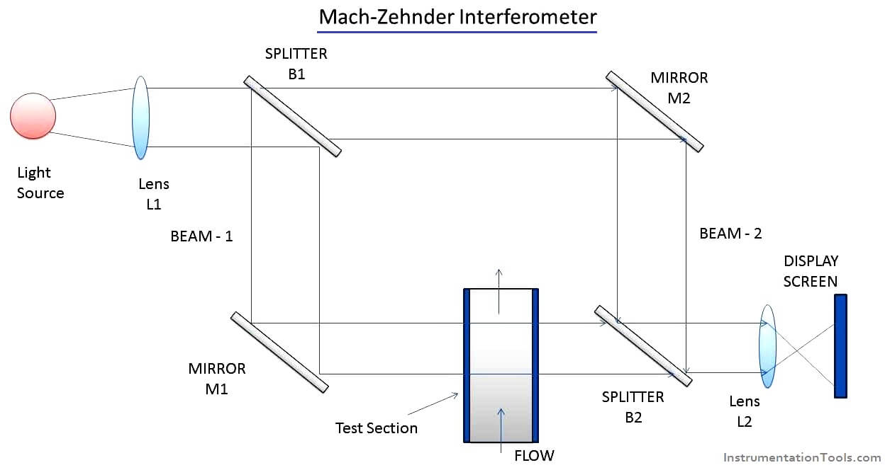
Interferometer PrincipleThe arrangement consists of the following:

  1. Two windows to form a test section
  2. A light source
  3. Two Lenses L1 and L2
  4. Two beam splitters B1 and B2
  5. Two mirrors M1 and M2
  6. A display Screen.

Operation of Interferometer

  1. Light rays from a source are collimated with a lens L1. That is, the light rays become a parallel beam of rays when they come out of the lens L1.
  2. These collimated light rays are then split by a beam splitter B1. The two beams traverse at right angles to each other.
  3. That is the beam splitter B1 makes half of the light to go to mirror M1. The remaining half is reflected towards mirror M2.
  4. Beam 1 is made to pass through the test section (to experience the flow filed) and beam 2 travels an alternate path, but of equal length.
  5. The two beams are again brought together with the help of beam splitter S2 and are then focused onto the display screen.
  6. Because of the variation in the refractive properties of the flowing gas in the test section, beams-1 will have a travel path of different optical length when compared to that of beam 2. Because of this, the two beams will be out of phase and will interface when they are joined together at B2. This causes alternate bright and dark regions called fringes on the display screen.
  7. The number of fringes will be a function of the difference in the optical length of the two beams. That is, for a difference in the path lengths of one wavelength, one fringe will appear. For a difference in the path lengths teo wave lengths, two fringes will appear and so on.
  8. It is to be noted that if medium I the test section has the same optical properties as that of the medium experience by beam 2, no fringe shifts will appear.
  9. Thus by observing ( and photographing) the interference effects, direct measurement of density variations of the flow in the test section can be obtained/ visualized.
  10. The only disadvantage in using this instrument is that it is difficult to align the setup to get beams that have travel paths of the same optical lengths.

If you liked this article, then please subscribe to our YouTube Channel for Instrumentation, Electrical, PLC, and SCADA video tutorials.

You can also follow us on Facebook and Twitter to receive daily updates.

Read Next:

  • Electromagnetic Flow Meters
  • Laser Doppler Anemometer
  • Doppler Ultrasonic Flow Meter
  • What is Insertion flow meters?
  • Coriolis Mass Meter Construction
Don't Miss Our Updates
Be the first to get exclusive content straight to your email.
We promise not to spam you. You can unsubscribe at any time.
Invalid email address
You've successfully subscribed !

Continue Reading

Flow Meter K-factor and Calculations
What is a Paddle Wheel Flow Meter?
Dall Tube Flow Meter – Principle, Advantages, Disadvantages
Electro-Magnetic Flow meter Objective Questions
Important Factors in Flow Measurement
Working Principle of Vortex Flow Meter
Share This Article
Facebook Whatsapp Whatsapp LinkedIn Copy Link
Share
Leave a Comment

Leave a Reply Cancel reply

Your email address will not be published. Required fields are marked *

Stay Connected

128.3kFollowersLike
69.1kFollowersFollow
210kSubscribersSubscribe
38kFollowersFollow

Categories

Explore More

Hot Wire Anemometer Principle and Types
Types of Flow Meters MCQ – Instrumentation and Control
Coriolis Flow Meter Uncertainty and Inaccuracy
What is an Orifice Flange? – Purpose and Applications
Difference between Fixed Area & Variable Area FlowMeters
Thermal Dispersion Flow Switch Working Principle
Importance of Magnetic Flow Meters Grounding
Coriolis Mass Flow Meter as a Multi-Variable Transmitter

Keep Learning

Turbine Flow Meter Animation

Turbine Flow Meter – Principle, Advantages, Disadvantages

Ultrasonic Doppler Flow Meter Advantages and Disadvantages

Ultrasonic Doppler Flow Meter Advantages and Disadvantages

Instrumentation Impulse Lines

All About Instrumentation Impulse Lines

Flow Transmitters Questions and Answers

Flow Transmitters Questions and Answers – Instruments Test

Weir Flow Meter Principle

Measure Flow rate using Level Sensors

Flow Switch Working

Flow Switch : What is it? – Applications

Comparison of Venturi and Orifice flow meterComparison of Venturi and Orifice flow meter

Comparison of Venturi and Orifice flow meter

DP-Flow-Transmitter-Re-Ranging-calculation

DP Flow Transmitter Re-Ranging Calculation

Learn More

Definitions of Electrical Grounding

Definitions of Electrical Grounding

PLC Programming Example on Multi-Motor Control for Beginners

PLC Programming Example on Multi-Motor Control for Beginners

Safety Valve

Compare Relief Valve and Safety Valve

Capacitor Bank

What is a Capacitor Bank?

Bipolar Junction Transistors Questions & Answers

Measurement and Instrumentation Objective Questions – Part 1

3-15 psi to 4-20mA Conversion

Example of 3-15 psi to 4-20mA Conversion

Barrier & Sensor Connection with NAMUR

Why we use NAMUR Output Sensor?

Self Actuated Pressure Control Valve Functional Testing

Self Actuated Pressure Control Valve Functional Testing

Menu

  • About
  • Privacy Policy
  • Copyright

Quick Links

  • Learn PLC
  • Helping Hand
  • Part Time Job

YouTube Subscribe

Follow US
All rights reserved. Reproduction in whole or in part without written permission is prohibited.
Welcome Back!

Sign in to your account

Username or Email Address
Password

Lost your password?