Inst ToolsInst ToolsInst Tools
  • Courses
  • Automation
    • PLC
    • Control System
    • Safety System
    • Communication
    • Fire & Gas System
  • Instrumentation
    • Design
    • Pressure
    • Temperature
    • Flow
    • Level
    • Vibration
    • Analyzer
    • Control Valve
    • Switch
    • Calibration
    • Erection & Commissioning
  • Interview
    • Instrumentation
    • Electrical
    • Electronics
    • Practical
  • Q&A
    • Instrumentation
    • Control System
    • Electrical
    • Electronics
    • Analog Electronics
    • Digital Electronics
    • Power Electronics
    • Microprocessor
  • Request
Search
  • Books
  • Software
  • Projects
  • Process
  • Tools
  • Basics
  • Formula
  • Power Plant
  • Root Cause Analysis
  • Electrical Basics
  • Animation
  • Standards
  • 4-20 mA Course
  • Siemens PLC Course
Reading: Interface Level Measurement Selection Guide
Share
Font ResizerAa
Inst ToolsInst Tools
Font ResizerAa
  • Courses
  • Design
  • PLC
  • Interview
  • Control System
Search
  • Courses
  • Automation
    • PLC
    • Control System
    • Safety System
    • Communication
    • Fire & Gas System
  • Instrumentation
    • Design
    • Pressure
    • Temperature
    • Flow
    • Level
    • Vibration
    • Analyzer
    • Control Valve
    • Switch
    • Calibration
    • Erection & Commissioning
  • Interview
    • Instrumentation
    • Electrical
    • Electronics
    • Practical
  • Q&A
    • Instrumentation
    • Control System
    • Electrical
    • Electronics
    • Analog Electronics
    • Digital Electronics
    • Power Electronics
    • Microprocessor
  • Request
Follow US
All rights reserved. Reproduction in whole or in part without written permission is prohibited.
Inst Tools > Blog > Instrumentation Design > Interface Level Measurement Selection Guide

Interface Level Measurement Selection Guide

Last updated: July 2, 2020 5:36 pm
Editorial Staff
Instrumentation Design Level Measurement
1 Comment
Share
1 Min Read
SHARE

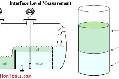
The table gives some guidance related to the oil-water interface level measurement for a single technology. However, it is important to understand the need for measurement. For some application, several technologies may be used to fix a need which cannot be solved by one technology only.

Interface Level Measurement

The table highlights some use cases but does not supersede the scope and limitation given in this recommended practice.

Interface Level Measurement Selection Guide

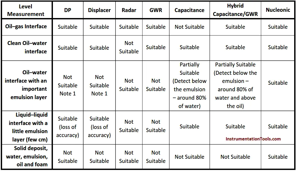
Table – Interface Measurement Selection Guidance

Note 1: The emulsion layer cannot be measured. The average density between the upper and lower density fluid may represent the emulsion density

Remark: All measurements may be challenged in the presence of dirty fluids (e.g. build‐up). The product often provides build‐up compensation functions.

Don't Miss Our Updates
Be the first to get exclusive content straight to your email.
We promise not to spam you. You can unsubscribe at any time.
Invalid email address
You've successfully subscribed !

Continue Reading

Ultrasonic Level Switch Working Principle
Difference between Axial and Radial Diaphragm Seal Connection?
Differential Pressure Level Transmitter Errors
Overview of Tank Gauging Technologies
How to Select a Directional Valves
Tilt Level Switch Working Principle
Share This Article
Facebook Whatsapp Whatsapp LinkedIn Copy Link
Share
1 Comment
  • Muralidharan says:
    July 17, 2018 at 4:54 am

    Sir how to review &verify instrument hookup diagram for erection

    Reply

Leave a Reply Cancel reply

Your email address will not be published. Required fields are marked *

Stay Connected

128.3kFollowersLike
69.1kFollowersFollow
210kSubscribersSubscribe
38kFollowersFollow

Categories

Explore More

Difference between Transparent Level Gauge and Reflex Level Gauge
Motor Control Center (MCC) Signal Interface Termination (SIT)
DP Level Transmitter with Zero Suppression Calibration
Industrial Automation Pre-Engineering Design Documents – Project & Process
Instrument Air Quality
Important Factors Consider during Piping Design
Open Tank Interface Level Measurement
15 Loop Diagram Questions

Keep Learning

Measuring Instruments

Flow Instruments – Selection, Principle & Application

Magnetic Level Gauge Float

Magnetic Level Gauge Float Design

Instrument Process Datasheet

Why is an Instrument Process Datasheet Required?

Instrumentation Design Details

I&C Engineer Roles & Responsibilities – Instrumentation Design

Capacitive Level Switch Principle

Capacitive Level Switch Principle

Bubbler Level Measurement System

Bubbler Level Sensor

Interface level Measurement

Interface Level Measurement using DP Transmitter

Float Level Switch Principle

Float Level Switch Working Principle Animation

Learn More

Delete Siemens CPU Memory

How to Delete the Siemens CPU Memory?

Transformers Questions & Answers Part-4

Transformers Questions & Answers Part-4

Relay Circuit for Hooter with Reset Button

Relay Latching Circuit using Push Button

SIS PFD - Safety Instrumented System

SIS PFD – Safety Instrumented System

Power Plant Interview Questions & Answers

Power Plant Interview Questions & Answers

pressure switch control two lamps wiring

Draw Wiring of a Pressure Switch to control two lamps

displacer level transmitter cylindrical weighs

Displacer Level Transmitter 5-point Calibration

Valve Standards

List of Valve Standards

Menu

  • About
  • Privacy Policy
  • Copyright

Quick Links

  • Learn PLC
  • Helping Hand
  • Part Time Job

YouTube Subscribe

Follow US
All rights reserved. Reproduction in whole or in part without written permission is prohibited.
Welcome Back!

Sign in to your account

Username or Email Address
Password

Lost your password?