We encounter many transmitters in daily activities like preventive maintenance, breakdown, or commissioning activities.
We may need to convert any given transmitter range to other range like from (0oC – 100oC) to (4 mA – 20 mA) or (0 kg/cm2 – 10 kg/cm2) to (3 psi – 15 psi) or (0 mmH2O – 2000 mmH2O) to (0% – 100%), etc.
Instrumentation Basics
All the above conversions are easy to implement. But now think of a case in which you are supposed to convert from (-250oC to 150oC) to (4 mA to 20 mA) or any such instrument range which has uneven starting and endpoints.
Don’t worry friends, in this article we will learn two methods to convert the value from one range to another range.
Instrument Range Conversion – Method 1
This method might be known to many engineers who are reading this article. But still, we don’t use it frequently because we often forget the formula.
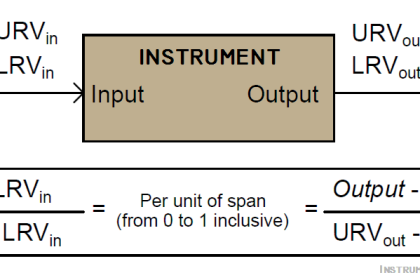
Every transmitter range has two parameters which are LRV and URV. Here LRV means lower range value and URV means upper range value.
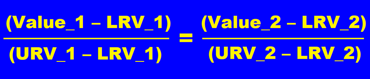
Let us recall the method. Suppose the first range is having LRV and URV as LRV_1 and URV_1 and another range has LRV_2 and URV_2.
Desired values are Value_1 and Value_2 in both ranges.
So, we use the below formula:
Let us see an example.
Suppose range one is 0 kg/cm2 – 100 kg/cm2
Range two is 4 mA to 20 mA
What will be value corresponding to 25 kg/cm2? (in milli amps)
Here Value_1 = 25
LRV_1 = 0
URV_1 = 100
Value_2 = to be calculated
LRV_2 = 4
URV_2 = 20
Put these values into the formula
(25-0) / (100-0) = ((Value_2) – 4) / (20-4)
25/100 = (Value_2 – 4) / 16
0.25 = (Value_2 – 4) / 16
Value_2 – 4 = 0.25 x 16
Value_2 = 4 + 4
Solving this equation, we get
Value_2 = 8
Hence for 25 kg/cm2, we get 8 mA as a proportional value.
This was quite an easy calculation that can even be done without using this formula.
Now have a look at the below example.
Range one: -70 o C to 190 o C
Range two: 4 mA to 20 mA
What will be the value corresponding to 50 o C? (in milli amps)
Put all values in our standard equation.
(50-(-70)) / (190-(-70)) = ((Value_2)-4) / (20-4)
120/260 = (Value_2 – 4)/16
0.4615 = (Value_2 – 4)/16
Value_2 – 4 = (0.4615 x 16)
Value_2 = 7.384 + 4
Solving this equation, we get
Value_2 = 11.384 mA
This is the first method.
Now let us see the second method which is for those who do not want to remember the formula.
Instrument Range Conversion – Method 2
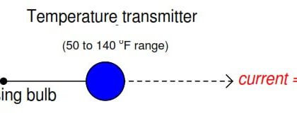
Let us see this method by taking an instrument example. Let us take the above example only
Range one: -70oC to 190oC
Range two: 4 mA to 20 mA
We need to calculate the equivalent milli amperes for the value of 50oC
First, calculate how much % is 50oC in the range of -70oC to 190oC.
The range is 260oC
For this we will use a simple formula :
50-(-70) —-> 260
? <—- 100
We have to take 50-(-70) because we want absolute value from LRV.
We get,
(100*120)/260 = 46.1538 %
Now we need a 46.1538% value for the 4 mA to 20 mA range
Divide the above value by 100. (46/100 = 0.461538)
Here 16 is the difference between URV and LRV.
So, multiply 0.461538 by 16. We get 7.3846.
Now add this value to our LRV. (7.3846 + 4)
We get 11.3846 mA which is our required value.
This is how we can convert values from one range to another.
If you liked this article, then please subscribe to our YouTube Channel for Instrumentation, Electrical, PLC, and SCADA video tutorials.
You can also follow us on Facebook and Twitter to receive daily updates.
Read Next:
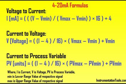
- 4 to 20 mA Formula
- Calculate Process Variable
- How to do 4-20mA Conversion
- Raw Counts to Engineering Units
- Turbine Flow meter Coefficient


I would love more training on all these courses
Thermocouple k and j type
. I know mv , how to find degree ? Formula
I know degree , how to find mv ? Formula
Please.