System architecture: applications and limitations for different use cases
This article gives an overview of several architectures for implementing remote functions. All architectures included in this article are for a general overview and illustrative purposes only. The specific design will be required for each implementation. A range of different architectures is included to provide an overview of the choices available. However, they do not represent all possible methods.
Architecture #1
Extension of the Local Network to a Remote Location

In this type of architecture, the Level 1 and 2 functions are extended to the remote location using a direct extension of the local system, using the same communication protocols as used on the local system networks.
As it is a horizontal extension, the conditions mentioned in the previous article (related to communication link security, performance, redundancy, diversity, protection of the remote location, site interdependencies, etc.) are to be considered. The management of the communication link and the remote devices need to follow the same security standard as the local IACS (patching, management of change, etc.).
This architecture requires low network latency and sufficient bandwidth to meet remote user requirements and vendor recommendations. Extensive testing to validate the architecture is recommended (including simulation of latency, route diversity, response to the loss of communications, etc.). This type of architecture is typically used for the operation of a plant from a remote control room. It is also a good architecture for remote engineering.
As described in the previous article, operational and organizational issues should be taken into consideration, especially how the transfer of authority is defined and controlled between the local and remote site.
Remote use of the SIS through the extension of safety networks through the telecom network link is possible by applying the black channel approach (IEC 61508-2). When remote SIS functionality is implemented in this way, actions to be taken locally in the event of loss of communication should be defined and programmed (timers before actions are taken, fail-safe state, etc.).
In addition, to ensure continued capability for local operations, it can be appropriate that the local safety system is not impacted by the loss of remote SIS nodes. Exact requirements will be defined by operational and safety objectives.
SIS connectivity depends on the safety philosophy or regulatory requirement. An alternative to this architecture – if allowed – would be to perform an interaction with SIS through HMI.
Architecture #2
Access to the Local System via Remote Display

In this type of architecture, the local functions are extended to a remote location using remote display sharing technology – for example, standard MS Windows RDP (or other remote display technology. The primary control and station are within the local site, and remote display technology is used to connect the remote user to a local workstation or server. The remote display access is performed on a dedicated Ethernet network.
As it is a horizontal extension, the conditions mentioned in the previous article (related to communication link security, performance, redundancy, diversity, protection of the remote location, etc.) are to be considered.
The management of the communication link and the remote devices need to follow the same security standard as the local IACS (patching, management of change).
The remote desktop technology will normally be useful when the bandwidth is low or latency is high.
Typically, this type of architecture is used for:
- Situation with telecom link performance limitations
- Remote engineering and maintenance
- Ad hoc/occasional remote control: compared to architecture #1, the remote displays are based on IT technology and are not natively designed to manage control functions.
- This architecture is normally useful when the use of remote function is ad hoc and not critical for the operation of the production site i.e. where lower response time and availability can be normally tolerated.
- For remote monitoring only purpose, other architectures (such as architecture #3 or #4) are better adapted.
Regarding safety functions, it needs to be considered that this architecture can provide interaction with SIS through HMI only (when typically, these are interacted with via a matrix panel).bpcs
The resilience to communication disturbance, the user experience (look and feel of the operator, including when link latency issues occur) and functionalities (resources management, authentication, etc.) needs to be taken into consideration in the choice of the selected remote display technology and tested.
If communication is interrupted, certain remote display technologies can buffer commands entered at a remote location and implement them once communications are restored. Behavior buffering should be tested, and settings should be made to avoid this problem. If this problem is present, the method will be restricted, and only monitoring should be allowed.
As described in the previous article, operational and organizational issues should consider how transfer of authority is defined and controlled between the local and remote site.
Architecture #3
Transfer of Data to Enterprise Level

This architecture is based on data transfer from a local historian to a data server located on a higher level. This architecture, by design, only provides a view on the data (and prevents interaction with the local system).
This architecture is typically used for the transfer of data from the IACS to Enterprise network for monitoring and analysis via specific applications (condition monitoring, predictive maintenance, process graphics, production planning, etc.)
The unidirectional flow of data can be ensured by a network security device such as a data diode or a firewall.
The interfaces into the IACS networks should be minimized to reduce threats from other zones.
As it is a vertical extension, the conditions mentioned in this article (in particular, those related to network segregation and segmentation) are to be applied.
Regarding monitoring-only systems (not connected to BPCS, SIS, or package), other options could be considered by the operator, based on a direct transfer to a higher level, subject to the fact that these systems would be isolated from the IACS, and considered as less critical.
Architecture #4
Access from Level 4 and above to DMZ Portal for view only

This type of architecture involves the installation of a portal server in the intermediate network or demilitarized zone (DMZ), with view-only functionality, that is meant to publish data or graphics which are built from the local IACS (Industrial Automation and Control System) system. Users located on the enterprise network can be authorized to access this portal to view the information. The access can be extended to the external networks outside the enterprise via specific corporate authentication and authorization mechanism to control access.
As it is a vertical extension, the conditions mentioned in this article (network segregation and segmentation, the requirement for authentication, etc.) are to be applied.
These portals can typically provide monitoring access to users located in the collaborative room, or to vendors to provide monitoring for maintenance and troubleshooting support. This type of architecture is the recommended solution to provide near real-time monitoring, to defined users.
The advantages of this architecture are that it does not allow direct interaction with an IACS system, and limits interaction to “read-only”. Most of these portals are based on web server technology and are expected to be resilient to telecom latencies. These portals are usually supplied by the same vendor that provides the system to be monitored.
These portals are designed to be “read-only”, but may require open ports for inbound traffic from DMZ to IACS that may contravene firewall rules policies.
Architecture #5
Access from an External Monitoring Center to Level 2 for view only

This architecture is sometimes used for remote equipment monitoring in the specific case of end-to-end managed services from vendor. Because of the proximity of the local station to the source data, this architecture enables remote specialists to view real-time operations.
The implementation of this architecture is complex, and the security of the access depends on the security measures applied at Vendor premises. If not configured or implemented correctly this solution will create a back door on the local system.
Firewalls capable of DPI (deep-packet-inspection) between the IACS controller and the local station are recommended. The main security features in this architecture include the use of secure tunnels (e.g., IPSec) from a local station at level 2 to a remote external monitoring center (the secure tunnel may use part of the infrastructure of higher levels).
Additionally, the Level 1 IACS device is protected against unauthorized modification using a DPI firewall that enforces unidirectional data flow. The firewall is configured such that access to the package system at Level 1 is read-only. Once set up, the firewall maintenance requirements will be minimal.
Additional traffic monitoring (by port mirroring) can be implemented to detect any malicious activity. This architecture can be viewed as a type of horizontal extension. It relies on the direct extension of networks to an external vendor monitoring center, and the conditions mentioned in this article (related to communication link security, protection of the remote location, etc.) should be applicable.
Contracts should be put in place to define the physical access and security restrictions at the Vendor premise at which the remote monitoring takes place (including access to data, limiting the access to specific devices) Network segregation should be implemented to prevent the propagation of threat between different customer sites that the vendor supports.
Architecture #6
Remote Access from Level 4 and above for Read and Write access

This type of architecture provides access from (potentially) anywhere to the local system via a specific platform located in DMZ that implements authentication management and resource management.
A user located on Level 4 or an external network authenticates on the platform, and can then access the resources and perform the actions they are authorized to during the permitted time (as described here).
This architecture is typically used for specific access for detailed investigations for troubleshooting (2nd level maintenance) and remote maintenance and engineering modifications. This solution is not recommended for general access to data and predictive maintenance (in that case, a read-only by design solution is preferred). Remote access of this type should be authorized to a limited number of remote users to access the minimum number of required internal devices.
As it is a vertical extension, the conditions mentioned in this article (network segregation and segmentation, the requirement for authentication, etc.) are to be considered. Risks related to the untrusted remote device should also be taken into consideration.
To avoid unauthorized and/or incorrect remote changes to critical systems, further restrictions can be enforced such that remote modifications are controlled by local personnel (as described here). Regarding monitoring-only systems (not connected to BPCS, SIS, or package), other options could be considered by the operator, based on direct access from higher levels, subject to the fact that these systems would be isolated from the IACS, and considered as less critical.
File transfer
For remote engineering and remote maintenance functions, file transfer may be needed from the remote user to the local station. These files could be software update files, configuration files, firmware updates, malware and antivirus update files, OS patch files, etc.
To access internal resources at the enterprise level and IACS, the remote user is required to be compliant to the applicable enterprise security policy (this can include anti-virus check, integrity check, etc.) Usually, the files are packed – compressed, encrypted and authored. The file can be sent from the remote user station to a file server located in DMZ.
In the DMZ, the file can be scanned and checked following the applicable security policy.
For example:
- Antivirus check. The use of a different antivirus software than that used on the remote station can add diversity of protection.
- Integrity can be checked via signature.
- The patch can be validated against the patching management database.
Once checked for compliance, the file can be transferred to a local file server in IACS (for example through SFTP). It is recommendable to transfer the file from DMZ to IACS via a request initiated by the IACS system administrator.
For operating system patching or antivirus file specific distribution service systems are mostly used.
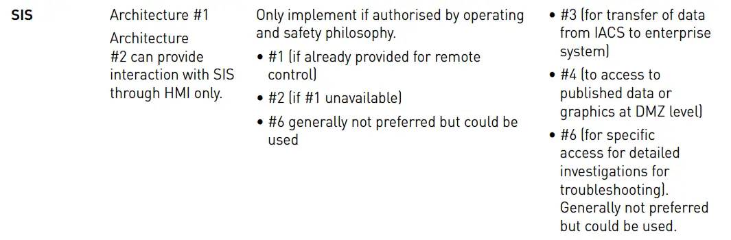
Recommended System Architectures
The following table summarises the main recommended architectures for different remote functions for the systems considered in this document. However, company policies may restrict or prohibit usage of specific architecture or certain remote functions.
- Architecture #1: Extension of the local network to a remote location
- Architecture #2: Access to the local system via remote display
- Architecture #3: Transfer of data to Enterprise level
- Architecture #4: Access from level 4 and above to DMZ portal for view only
- Architecture #5: Access from an external monitoring center to level 2 for view only
- Architecture #6: Remote access from level 4 and above for read and write access


Example of Hybrid Architecture Implementation
This figure illustrates one example of the implementation of a possible hybrid architecture for an onshore remote control center of an offshore production site.

Source: International Association of Oil & Gas Producers
Acknowledgments: IOGP Instrumentation and Automation Standards Subcommittee (IASSC) Remote Operating Centres Task Force.
Read Next:
- Distributed Control System
- Functions of PID Controller
- How to Test Control Loop?
- Basic Process Control System
- Design Guide of Control Room