Learn the concept of Increment & Decrement Instructions and examples in Omron PLC using CX-Programmer software.
Increment & Decrement Instructions
Increment and Decrement Instructions are widely used in industrial automation PLC programs because of their ease of data processing.
Increment and Decrement Instructions have the same function as the Counter function, namely as “Counters”. Increment Instructions function to increase the amount of data while Decrement Instructions function to decrease the amount of data stored in Word Memory allocation.
Unlike the Counter Instruction, the Increment and Decrement Instructions do not require SV (Set Value) parameters because the purpose of the Increment and Decrement Instructions is to hold data, raise data, and lower data.
Generally, these two instructions are used in conjunction with “Comparison Data” Instructions such as (=, <,>, >=, <=, <>).
Types of OMRON Instructions
Increment and Decrement instructions on CX-Programmer have several types, as follows:
- ++(590) Binary Increment
- ++L(591) Double Increment Binary
- –(592) Decrement Binary
- –L(593) Double Decrement Binary
- ++B(594) Increment BCD
- ++B(595) Double Increment BCD
- –B(596) Decrement BCD
- –BL(597) Double Decrement BCD
In this article, we will only discuss the increment & Decrement instructions of Binary types.
Binary type increment & Decrement instructions use Binary numbers in increasing and decreasing the data, but the data presented/displayed can be in other units, Hexadecimal for example.
Increment & Decrement Binary Instruction Type
There are 2 types of Binary increments, namely “++(590)” and “@++(590)”. Both types have the same function to increase the amount of data in increments per +1 BIN. The difference are explained in the following 2 figures.
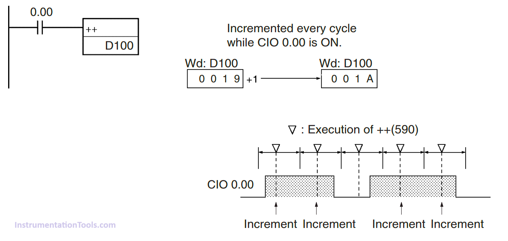
In the picture above is an Increment Instruction type “++(590)”, when the Input contact (0.00) is activated for a long time the value in the data allocation “D100” will increase continuously, with changes in the addition of data values per program cycle.
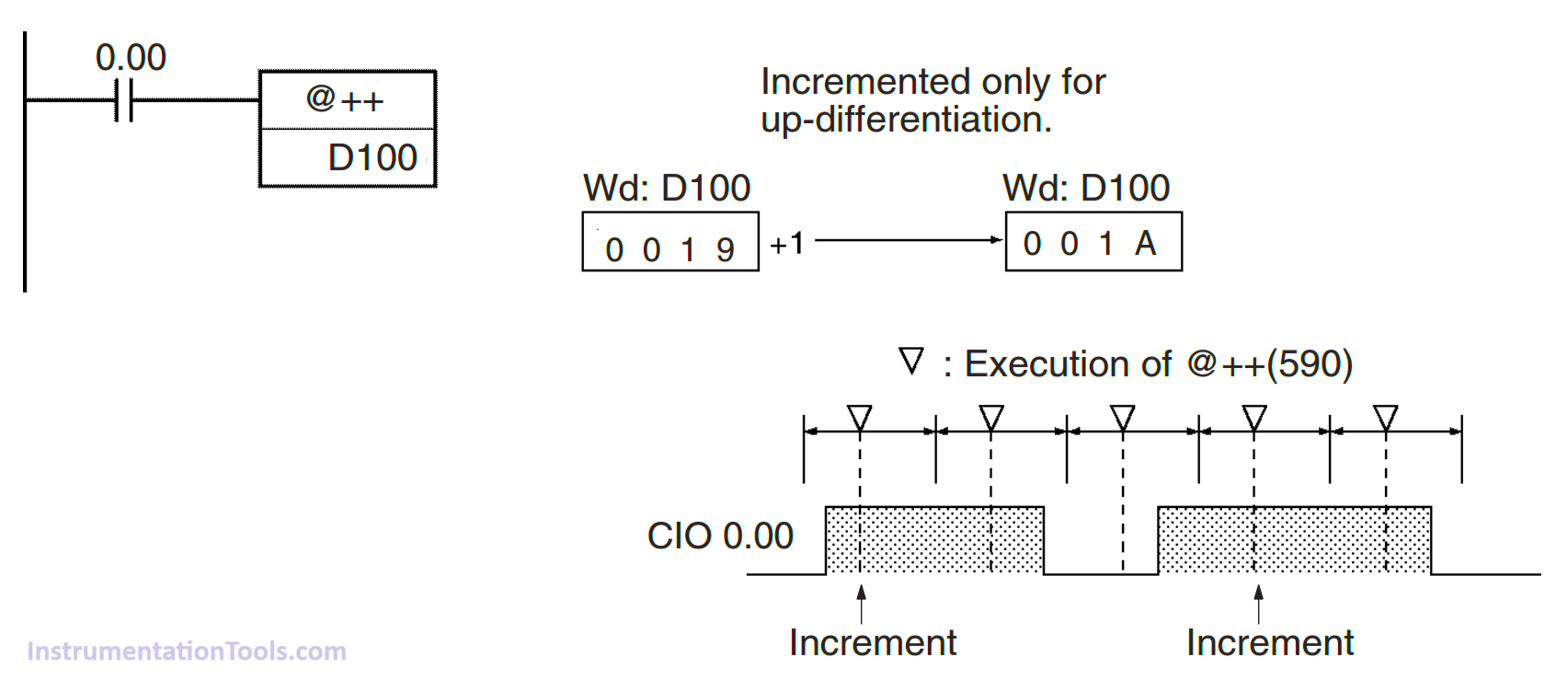
The second picture is an Increment Instruction of type “@++(590)“, the difference is that the increase in value in memory allocation “D100” only occurs once when the contact changes (0.00) from the “OFF” to “ON” condition, even if the contact is activated for a long time, the value will not increase, because this Instruction uses the concept of Differentiate Up in adding its value.
The Decrement Binary instruction also has 2 types, namely “–(592)” and “@–(592)”. Both types have the same function to reduce the amount of data with a decrease in data by -1 BIN. The differences between the two types are explained in the following next 2 figures.
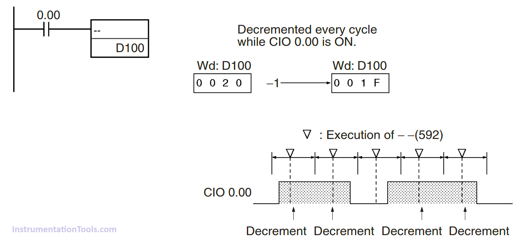
In the picture above, it is the Decrement Instruction type “–(592)”, when the Input contact (0.00) is activated for a long time the value on the data allocation “D100” will decrease continuously, with changes in data values decreasing per program cycle.
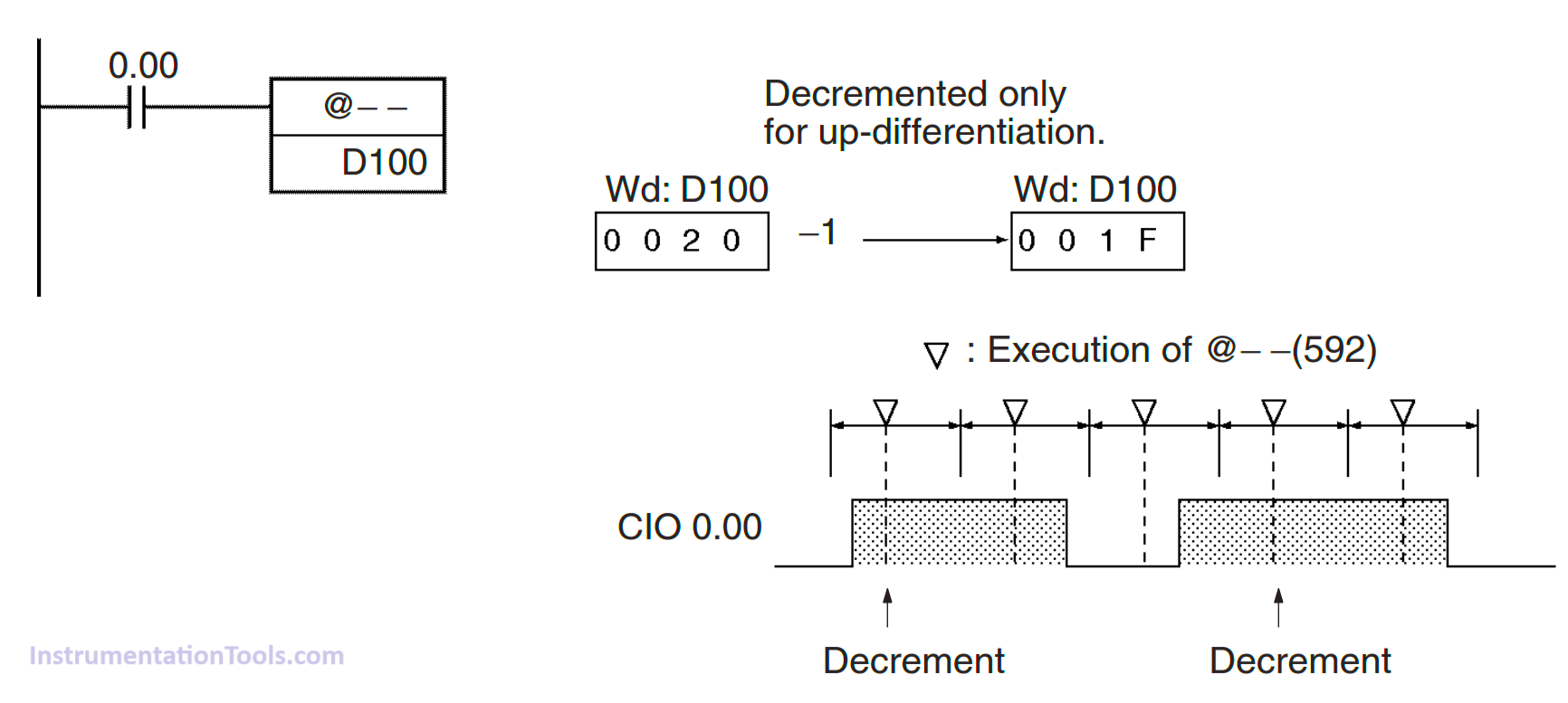
The second picture is an Increment Instruction of type “@–(592)”, a decrease in the value of data on the memory allocation “D100” occurs only once when the contact changes (0.00) from the “OFF” to “ON” condition, even if the contact is activated for a long time the value will not decrease because this Instruction uses the concept of Differentiate Up in decreasing its value.
Addressing Memory Increment & Decrement in CX-Programmer
The table below contains the memory allocation areas that can be used by Increment and Decrement instructions.
| Area | Wd |
| CIO Area | CIO 0 to CIO 6143 |
| Work Area | W0 to W511 |
| Holding Bit Area | H0 to H511 |
| Auxiliary Bit Area | A448 to A959 |
| Timer Area | T0000 to T4095 |
| Counter Area | C0000 to C4095 |
| DM Area | D0 to D32767 |
| Indirect DM addresses in binary | @ D0 to @ D32767 |
| Indirect DM addresses in BCD | *D0 to *D32767 |
| Constants | — |
| Data Registers | DR0 to DR15 |
| Index Registers | — |
| Indirect addressing using Index Registers | ,IR0 to ,IR15 –2048 to +2047, IR0 to –2048 to +2047, IR15 DR0 to DR15, IR0 to IR15 ,IR0+(++) to ,IR15+(++) ,–(– –)IR0 to, –(– –)IR15 |
CX-Programmer Program
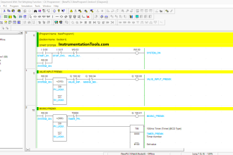
In this program, 2 experiments were carried out using 2 types of Binary Increment & Decrement Instructions to find out the difference between them.
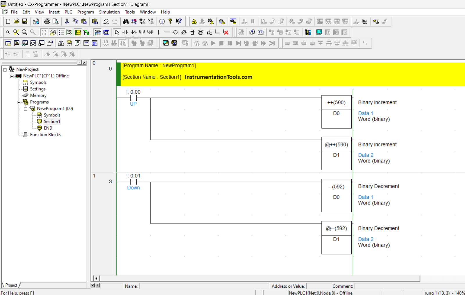
In the image, the program consisting of 2 Rungs, Rung 0 contains 2 types of increment Instructions “++(590)” with memory allocation (D0) and another instruction “@++(590)” with memory allocation (D1).
Rung 1 using Decrement “–(592)” instruction using memory allocation (D0) and another instruction “@–(592)” using memory allocation (D1).
Simulation Results
When simulated, the difference can be seen, when the UP contact (0.00) is activated and the value of (D0) rises very high while the value of (D1) only increases by 1 data.
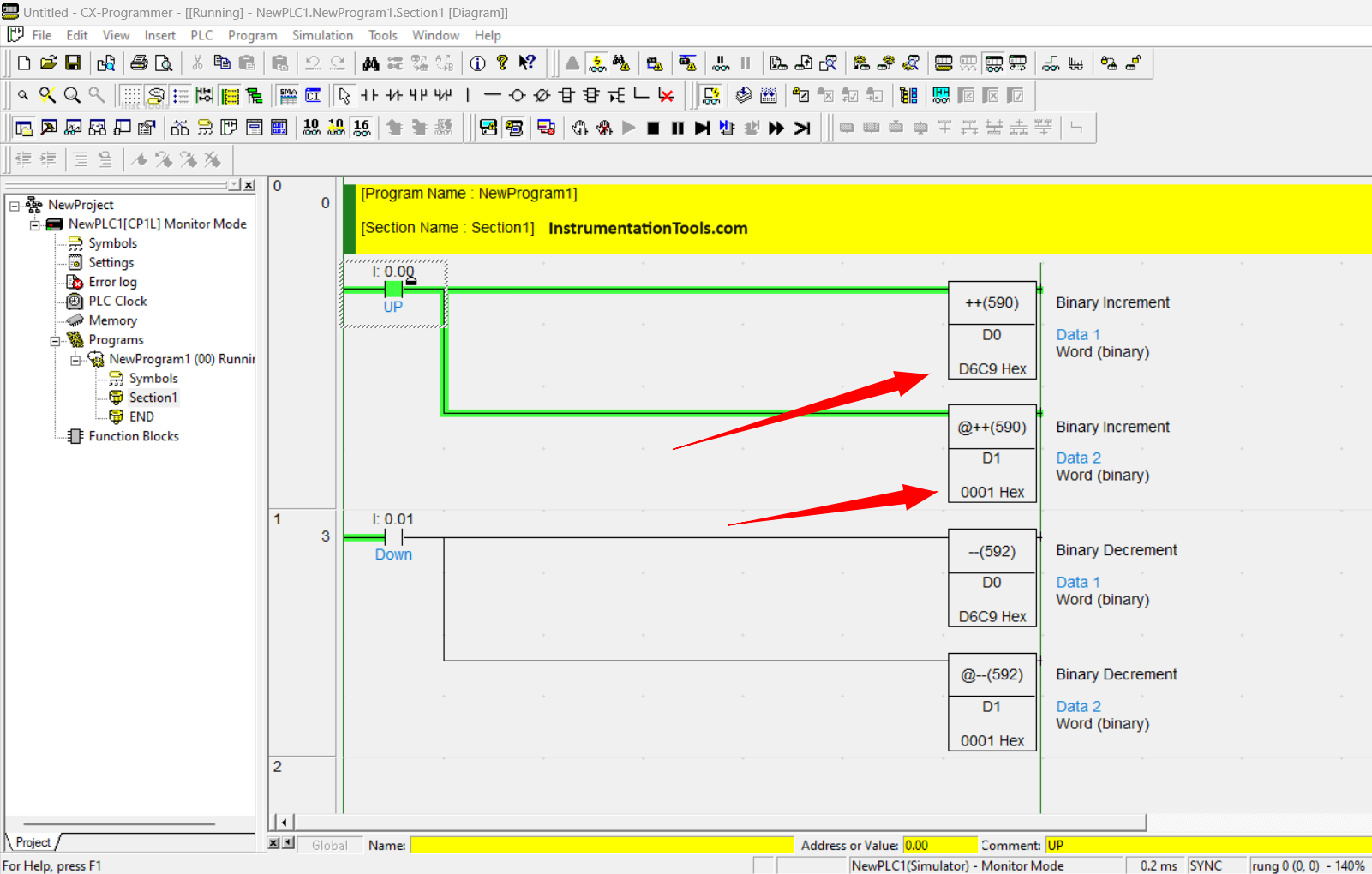
This is because the Cyclic program process has occurred many times so that the value at (D0) is very high and the value at (D1) only increases by 1 data because the increase in data value only occurs when the UP contact condition changes (0.00) from “OFF” to “ON”.
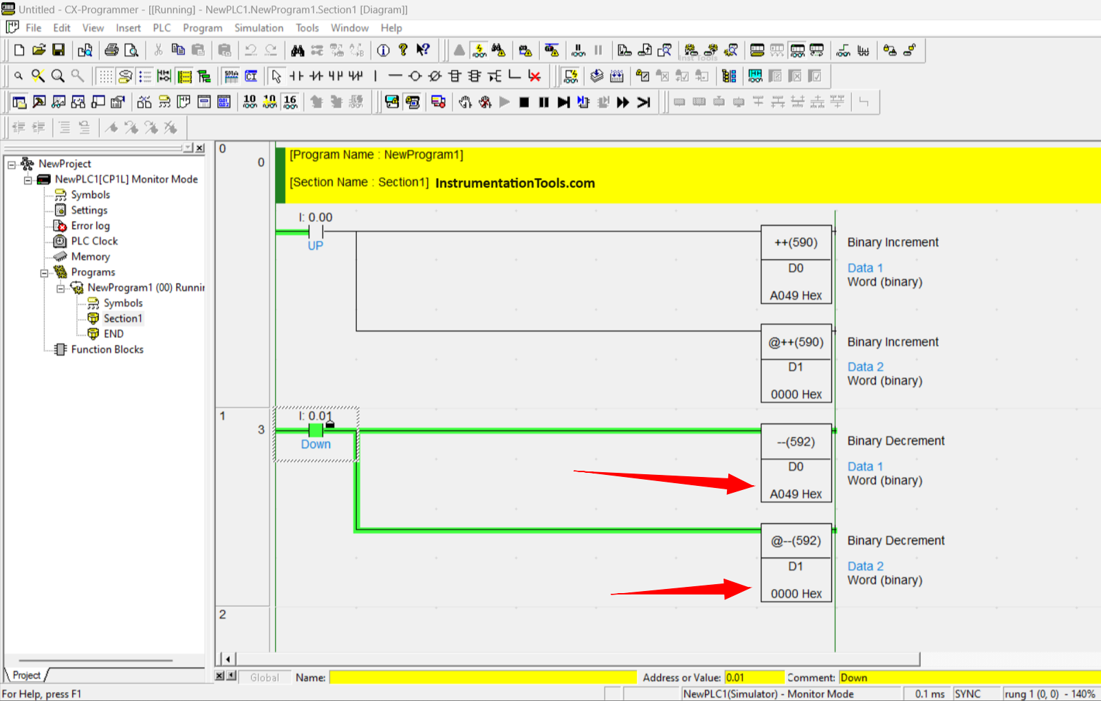
When the Down contact (0.01) is activated the value of (D0) will drop quite a lot, while the value of (D1) will drop by 1 data only.
If you liked this article, please subscribe to our YouTube Channel for PLC and SCADA video tutorials.
You can also follow us on Facebook and Twitter to receive daily updates.
Read Next:
- What are High-Speed Inputs in PLC?
- PLC Exercise on Door Lock with Delay
- Difference between Timer and Counter
- How to use Real-Time Clock in Omron PLC?
- Pumping and Draining PLC Program System