Inst ToolsInst ToolsInst Tools
  • Courses
  • Automation
    • PLC
    • Control System
    • Safety System
    • Communication
    • Fire & Gas System
  • Instrumentation
    • Design
    • Pressure
    • Temperature
    • Flow
    • Level
    • Vibration
    • Analyzers
    • Control Valve
    • Switch
    • Calibration
    • Formula
    • Erection & Commissioning
    • Process Fundamentals
    • Root Cause Analysis
  • Q&A
    • Instrumentation
    • Electrical
    • Electronics
    • Practical
  • MCQ
    • Multiple Choice Questions
    • Instrumentation MCQ
    • Electrical MCQ
    • Digital Electronics MCQ
    • Microprocessor MCQ
    • Control Systems MCQ
    • Electronics MCQ
    • Analog Electronics MCQ
    • Power Electronics MCQ
Search
All rights reserved. Reproduction in whole or in part without written permission is prohibited.
Reading: Impeller Flow Sensor Working Principle and Animation
Share
Notification Show More
Font ResizerAa
Inst ToolsInst Tools
Font ResizerAa
  • Courses
  • PLC
  • Control Systems
Search
  • Courses
  • Automation
    • PLC
    • Control System
    • Safety System
    • Communication
    • Fire & Gas System
  • Instrumentation
    • Design
    • Pressure
    • Temperature
    • Flow
    • Level
    • Vibration
    • Analyzers
    • Control Valve
    • Switch
    • Calibration
    • Formula
    • Erection & Commissioning
    • Process Fundamentals
    • Root Cause Analysis
  • Q&A
    • Instrumentation
    • Electrical
    • Electronics
    • Practical
  • MCQ
    • Multiple Choice Questions
    • Instrumentation MCQ
    • Electrical MCQ
    • Digital Electronics MCQ
    • Microprocessor MCQ
    • Control Systems MCQ
    • Electronics MCQ
    • Analog Electronics MCQ
    • Power Electronics MCQ
Follow US
All rights reserved. Reproduction in whole or in part without written permission is prohibited.
Inst Tools > Blog > Animation > Impeller Flow Sensor Working Principle and Animation

Impeller Flow Sensor Working Principle and Animation

Impeller Flow Sensor have magnets which actuate Hall effect switches to detect impeller rotation and this is proportional to flow rate.

Last updated: October 31, 2023 11:13 am
Editorial Staff
Animation Flow Measurement How It Works
2 Comments
Share
1 Min Read
SHARE

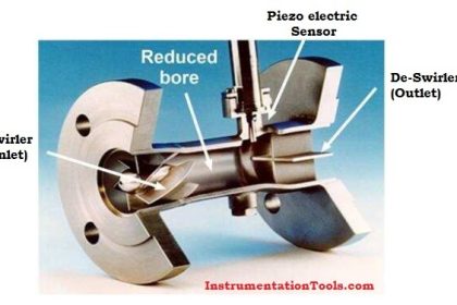
Impeller Flow Sensor probes are equipped with lightweight helical impellers mounted on double sapphire bearings.

The impellers contain magnets that actuate Hall-effect switches within the probe to detect impeller rotation. The impeller rotation is proportional to the flow rate.

Impeller Flow Sensor

Impeller Flow Sensor

If you liked this article, then please subscribe to our YouTube Channel for Instrumentation, Electrical, PLC, and SCADA video tutorials.

You can also follow us on Facebook and Twitter to receive daily updates.

Read Next:

  • Microwave Flow Sensor
  • Flow Measurement Techniques
  • Vortex Flow Meter Animation
  • Different Types of Flow Sensors
  • Lobed Impeller Flow Meters
Don't Miss Our Updates
Be the first to get exclusive content straight to your email.
We promise not to spam you. You can unsubscribe at any time.
Invalid email address
You've successfully subscribed !

Continue Reading

What is a Positive Displacement Flow Meter?
PLC Sinking and Sourcing Explanation
Magnetic Flow Meters Installation Guidelines
What is Differential Pressure Flow Meter?
Thermocouple Working Principle
Basics of Flow Measurement
Share This Article
Facebook Whatsapp Whatsapp LinkedIn Copy Link
Share
2 Comments
  • Sesykamal says:
    September 7, 2015 at 1:25 pm

    Instrumentation tools created by BHARADWAJ GARU is very useful to us about subject and for future interviews. Thank you,BHARADWAJ GARU

    Reply
  • Shaju says:
    September 8, 2015 at 7:58 am

    With impeller measuring element,flow can be quickly detected.
    Thank you sir , for the information.

    Reply

Leave a Reply Cancel reply

Your email address will not be published. Required fields are marked *

Stay Connected

128.3kFollowersLike
69.1kFollowersFollow
208kSubscribersSubscribe
38kFollowersFollow

Categories

Explore More

All About Variable Area Flow Meters
Guided-wave Radar Level Measurement Animation
Relay Principle & its Types
Turbine Flow Meter Installation Procedure
Microwave Flow Sensor – Working Principle and Applications
How a Level Switch Works
Non Contacting Radar Level Transmitter Animation
What is Seal-in Circuit ?

Keep Learning

Flow Transmitters Questions and Answers

Flow Transmitters Questions and Answers – Instruments Test

Piston Type Flow Meter Principle

Types of Variable Area Flow Meters

Turbine Flow Meter Calibration

How to do Turbine Flow Meter Verification?

Turbine Flow Meter

All About Turbine Meters

Flow Switch Working

Flow Switch : What is it? – Applications

Motor contactors

What is Contactor ?

Two Wire Sensors Animation

Two Wire Sensor Working Principle and Animation

LVDT-Operation-Principle-Animation

LVDT Working Principle Animation

Learn More

Open Tank Level Measurement using DP Transmitter

Open Tank Level Measurement using DP Transmitter

Solid State Devices Objective Questions and Answers

Top 300 Solid State Devices Objective Questions and Answers

Instrument Technician Interview Questions

Instrument Technician Interview Questions and Answers

Dual-beam non-dispersive analyzer

Dual-beam Non-dispersive Analyzer

Types of Control Valves

Fundamentals of Valves and their Types

Profibus Communication Interview Questions & Answers

Profibus Communication Interview Questions & Answers

Difference Between Microcontroller and Microprocessor

Difference Between Microcontroller and Microprocessor

Connection between PLC and Contactor

Contactor – Basics, Wiring, Connection with PLC

Follow US
All rights reserved. Reproduction in whole or in part without written permission is prohibited.
Welcome Back!

Sign in to your account

Username or Email Address
Password

Lost your password?