A detrimental effect to feedback control is a characteristic known as hysteresis: a lack of responsiveness to a change in direction. Although hysteresis typically resides with instruments rather than the physical process they connect to, it is most easily detected by a simple open-loop (“stepchange”) test with the controller in manual mode just like all the important process characteristics (self-regulating versus integrating, steady-state gain, lag time, dead time, etc.).
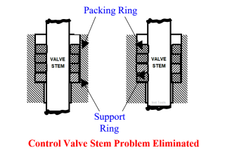
The most common source of hysteresis is found in pneumatically-actuated control valves possessing excess stem friction. The “jerky” motion of such a valve to smooth increases or decreases in signal is sometimes referred to as stiction. Similarly, a pneumatically-actuated control valve with excess friction will be unresponsive to small reversals in signal direction. To illustrate, this means the control valve’s stem position will not be the same at a rising signal value of 50% (typically 12 mA, or 9 PSI) as it will be at a falling signal value of 50%.
Control valve stiction may be quite severe in valves with poor maintenance histories, and/or lacking positioners to correct for deviations between controller signal value and actual stem position. I have personally encountered control valves with hysteresis values in excess of 10% , and have heard of even more severe cases.
Detecting hysteresis in a control loop is as simple as performing “up-and-down” tests of the controller output signal in manual mode. The following trend shows how hysteresis might appear in a self-regulating process such as liquid flow control:
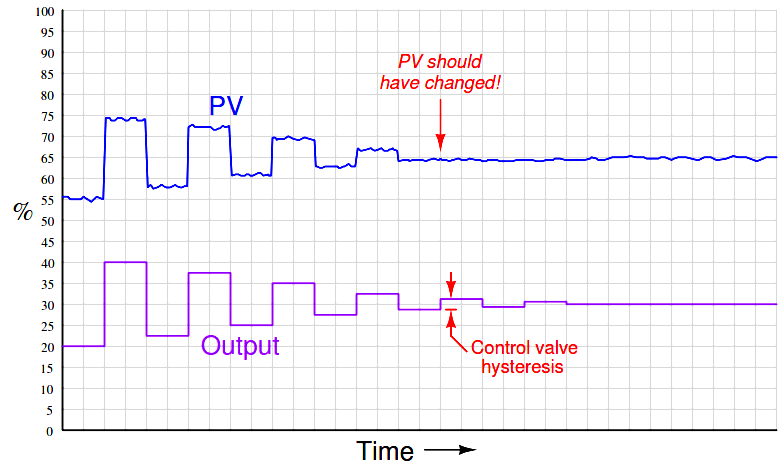
Note how the PV responds to large up-and-down output step-changes, but stops responding as soon as the magnitude of these open-loop step-changes falls below a threshold equal to the control valve’s hysteresis.
Applied to an integrating process such as liquid level control, the same type of test reveals the control valve’s hysteresis by the largest step-change that does not alter the PV’s slope:
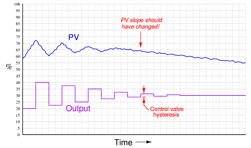
It is not as simple to perform this test on a process with slow lag or dead times, of course, or on a process possessing a “runaway” (rather than self-regulating or integrating) characteristic, in which case a better test for valve hysteresis would be to monitor valve stem position rather than the PV when executing the step-changes.
Hysteresis is a problem in feedback control because it essentially acts like a variable dead time. Recall that “dead time” was defined as a period of time during which a change in manipulated variable produces no effect in the process variable: the process appears “dead” for some amount of time before showing a response. If a change in controller output (manipulated variable) is insufficient to overcome the hysteresis inherent to a control valve or other component in a loop, the process variable will not respond to that output signal change at all. Only when the manipulated variable signal continues to change sufficiently to overcome hysteresis will there be a response from the process variable, and the time required for that to take place depends on how soon the controller’s output happens to reach that critical value. If the controller’s output moves quickly, the “dead time” caused by hysteresis will be short. If the controller’s output changes slowly over time, the “dead time” caused by hysteresis will be longer.
Another problem caused by hysteresis in a feedback loop occurs in combination with integral action, whether it be programmed into the controller or is inherent to the process (i.e. an integrating process). It is highly unlikely that a “sticky” control valve will happen to “stick” at exactly the right stem position required to equalize PV and SP. Therefore, the probability at any time of an error developing between PV and SP, or of an offset developing between the valve position and the equilibrium position required by an integrating process, is very great. This leads to a condition of guaranteed instability. For a self-regulating process with integral action in the controller, the almost guaranteed existence of PV − SP error means the controller output will ceaselessly ramp up and down as the valve first slips and sticks to give a positive error, then slips and sticks to give a negative error. For an integrating process with proportional action in the controller, the process variable will ceaselessly ramp up and down as the valve first sticks too far open, then too far closed to equalize process in-flow and out-flow which is necessary to stabilize the process variable. In either case, this particular form of instability is called a slip-stick cycle.
The following process trend shows a slip-stick cycle in a self-regulating process, controlled by an integral-only controller:
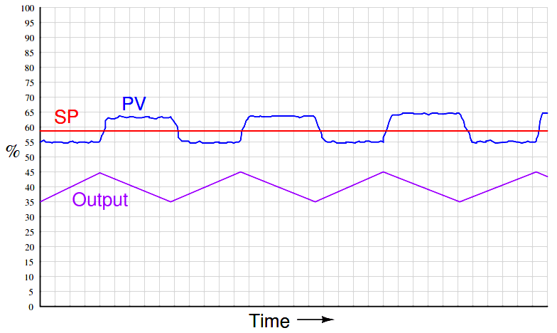
Note how the output ceaselessly ramps in a futile attempt to drive the process variable to setpoint. Once sufficient pressure change accumulates in the valve actuator to overcome static stem friction, the valve “slips to and sticks at” a new stem position where the PV is unequal to setpoint, and the controller’s integral action begins to ramp the output in the other direction.
The next trend shows a slip-stick cycle in an integrating process, controlled by a proportional-only controller:
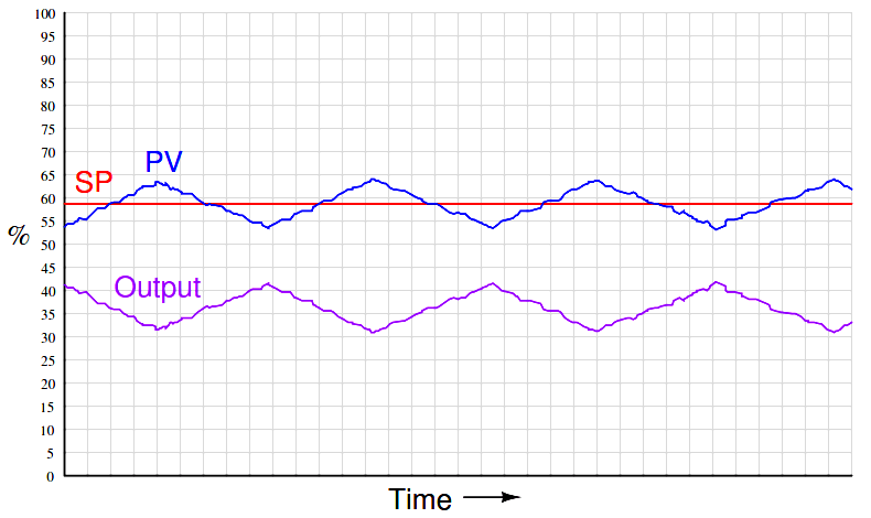
Note how the process variable’s slope changes every time the valve “slips to and sticks at” a new stem position unequal to the balance point for this integrating process. The process’s natural integrating action then causes the PV to ramp, causing the controller’s proportional action to similarly ramp the output signal until the valve has enough accumulated force on its stem to jump to a new position.
It is very important to note that the problems created by a “sticky” control valve cannot be completely overcome by controller tuning. For instance, if one were to de-tune the integral-only controller (i.e. longer time constant, or fewer repeats per minute) in the self-regulating process, it would still exhibit the same slip-stick behavior, only over a longer period (lower frequency) than before. If one were to de-tune the proportional-only controller (i.e. greater proportional band, or less gain) in the integrating process, the exact same thing would happen: a decrease in cycle frequency, but no elimination of the cycling. Furthermore, de-tuning the controller in either process would also result in less responsive (poorer) corrective action to setpoint and load changes. The only solution to either one of these problems is to reduce or eliminate the friction inside the control valve.