Inst ToolsInst ToolsInst Tools
  • Courses
  • Automation
    • PLC
    • Control System
    • Safety System
    • Communication
    • Fire & Gas System
  • Instrumentation
    • Design
    • Pressure
    • Temperature
    • Flow
    • Level
    • Vibration
    • Analyzer
    • Control Valve
    • Switch
    • Calibration
    • Erection & Commissioning
  • Interview
    • Instrumentation
    • Electrical
    • Electronics
    • Practical
  • Q&A
    • Instrumentation
    • Control System
    • Electrical
    • Electronics
    • Analog Electronics
    • Digital Electronics
    • Power Electronics
    • Microprocessor
  • Request
Search
  • Books
  • Software
  • Projects
  • Process
  • Tools
  • Basics
  • Formula
  • Power Plant
  • Root Cause Analysis
  • Electrical Basics
  • Animation
  • Standards
  • 4-20 mA Course
  • Siemens PLC Course
Reading: Hydrostatic Level Measurement – Temperature related Density Change Effects
Share
Font ResizerAa
Inst ToolsInst Tools
Font ResizerAa
  • Courses
  • Design
  • PLC
  • Interview
  • Control System
Search
  • Courses
  • Automation
    • PLC
    • Control System
    • Safety System
    • Communication
    • Fire & Gas System
  • Instrumentation
    • Design
    • Pressure
    • Temperature
    • Flow
    • Level
    • Vibration
    • Analyzer
    • Control Valve
    • Switch
    • Calibration
    • Erection & Commissioning
  • Interview
    • Instrumentation
    • Electrical
    • Electronics
    • Practical
  • Q&A
    • Instrumentation
    • Control System
    • Electrical
    • Electronics
    • Analog Electronics
    • Digital Electronics
    • Power Electronics
    • Microprocessor
  • Request
Follow US
All rights reserved. Reproduction in whole or in part without written permission is prohibited.
Inst Tools > Blog > Practical Questions > Hydrostatic Level Measurement – Temperature related Density Change Effects

Hydrostatic Level Measurement – Temperature related Density Change Effects

Last updated: September 28, 2018 3:37 pm
Editorial Staff
Practical Questions
2 Comments
Share
4 Min Read
SHARE

Hydrostatic Level Measurement – Temperature related Density Change

Question :

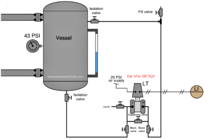
An open vessel contains water at 60 oF. A pressure transmitter located at the bottom of the vessel measures the hydrostatic pressure (“head”) generated by the water and outputs a signal corresponding to level. Suppose that the temperature of this vessel were to increase over time to 110 oF due to exposure to very hot outside air.

Knowing that an increase in water temperature will result in a decrease in density, what will happen to the level transmitter’s output as the vessel heats up? Will the transmitter output increase, decrease, or stay the same? Why?? Assume that no water enters or exits the vessel during the period of heating from 60 oF to 110 oF.

Answer :

The transmitter output will stay the same.

If you thought that the transmitter output would decrease due to the water becoming less dense, I recommend you explore the concept of density a little deeper with the following “thought experiment:”

  • Imagine the vessel filled half-way with liquid.
  • Imagine that liquid heating up and expanding until it is only half as dense as it was at the beginning of the experiment.
  • Calculate the new hydrostatic pressure with the expanded, less-dense liquid.

In a way, this is a “trick” question. As any given mass of water heats up, its volume will increase. This is what makes it less dense than before: increased volume with the same mass (weight). Knowing how to calculate hydrostatic pressure from height and specific gravity, you might have approached this problem by assuming the water column height would have stayed the same while its density decreased, resulting in a lesser hydrostatic pressure and decreased transmitter output. However, this answer is incorrect.

If the water volume expands as a result of a temperature increase, the level inside the vessel must rise, because it will require a higher vessel level to contain a greater volume of water. The level will rise by the same percentage that the density decreases, resulting in a cancellation of level increase with density decrease. As a result, the hydrostatic pressure at any point in the vessel remains constant.

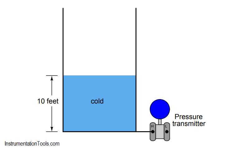
If you have difficulty picturing this effect, consider an exaggerated example to make things simpler. Suppose that a vessel has been filled to a height of 10 feet with cold liquid:

hydrostatic pressure Transmitter Calculations

Now, imagine that same vessel being heated until the liquid expands to exactly twice its former volume:

liquid level Measurement

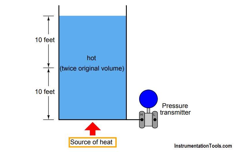
The liquid level must double to accommodate twice the volume in the same vessel, assuming a vessel of constant diameter, and its density will be cut in half (twice the volume with the same mass). Consequently, the two factors of liquid level change and liquid density change cancel each other out to give the exact same hydrostatic pressure as before.

In other words, the transmitter will register the same liquid level as it did when the liquid was cold, and will output the exact same signal, even though the actual vessel level is quite a bit more than it was when cold. Pretty tricky, huh?

Note : This concept applies to this particular case study/question. In most cases temperature effects the DP Transmitter readings especially if it is capillary type.

Also Read : Hydrostatic Interface Level Measurement

Don't Miss Our Updates
Be the first to get exclusive content straight to your email.
We promise not to spam you. You can unsubscribe at any time.
Invalid email address
You've successfully subscribed !

Continue Reading

Baffle Nozzle Question
Pressure Transmitter Re-Range Questions
Calculate the Transmitter Values
Process Control High Level Alarm Fault Analysis
PLC connected to Three Pushbutton Switches
How to Connect Proximity Switch (Source Type) to Make LED ON ?
Share This Article
Facebook Whatsapp Whatsapp LinkedIn Copy Link
Share
2 Comments
  • nishtha says:
    June 6, 2018 at 12:45 am

    Please show its mathematical proof.

    Reply
  • sagar says:
    June 6, 2018 at 8:50 am

    For mathematical proof please refer A.K.sawhney measurement book and k. krishnaswamy industrial instrumentation.
    for more help put your question on my [email protected]

    Reply

Leave a Reply Cancel reply

Your email address will not be published. Required fields are marked *

Stay Connected

128.3kFollowersLike
69.1kFollowersFollow
210kSubscribersSubscribe
38kFollowersFollow

Categories

Explore More

Which Instrument is at Fault in this System?
DP Transmitter Located 10 feet Beneath the Vessel
Determine the Status of Lamps and Relays in the Circuit ?
Is it Possible to Measure Liquid-Liquid Level Interface using Float?
What Affect the Pressure Measurement Accuracy of a Manometer?
As per Process Conditions, Find out the Circuit Components Status ?
Identify the Purpose of Flow Ratio Controller
Programmable Logic Controller (PLC) Questions and Answers – 7

Keep Learning

Three-valve Manifold on Remote Seal DP Transmitter

Three-valve Manifold on Remote Seal DP Transmitter

Air Compressor Control Circuit has a Problem

Air Compressor Control Circuit Problem

compressor emergency shutdown system

Compressor Emergency Shutdown Root Cause Analysis

displacer level transmitter cylindrical weighs

Displacer Level Transmitter 5-point Calibration

water filter level control system

Practical Process Control System Questions & Answers – 6

level control system

Practical Process Control System Questions & Answers – 11

Drum Level differential pressure transmitter

Calculate Differential Pressure Sensed by Level Transmitter

Calculate the Magnitude of Hydrostatic Pressure

Calculate the Magnitude of Hydrostatic Pressure

Learn More

Power Systems Questions & Answers

Power Systems MCQ Series 18

Common Causes of Imperfect Bends

Instrument Tube Fitting Installation – Part 3

Digital Electronics Multiple Choice Questions

Multivibrators Objective Questions

Things to Know When Measuring Voltage

Things to Know When Measuring Voltage

Problem on Solar Hot Air Collector and Variable Speed Fan

Problem on Solar Hot Air Collector and Variable Speed Fan

Raspberry Pi Projects

200 Raspberry Pi Projects

microwave flow detector applications

Microwave Flow Sensor – Working Principle and Applications

Single Line Diagram of UPS System

UPS Selection Factors for a Control System

Menu

  • About
  • Privacy Policy
  • Copyright

Quick Links

  • Learn PLC
  • Helping Hand
  • Part Time Job

YouTube Subscribe

Follow US
All rights reserved. Reproduction in whole or in part without written permission is prohibited.
Welcome Back!

Sign in to your account

Username or Email Address
Password

Lost your password?