Inst ToolsInst ToolsInst Tools
  • Courses
  • Automation
    • PLC
    • Control System
    • Safety System
    • Communication
    • Fire & Gas System
  • Instrumentation
    • Design
    • Pressure
    • Temperature
    • Flow
    • Level
    • Vibration
    • Analyzer
    • Control Valve
    • Switch
    • Calibration
    • Erection & Commissioning
  • Interview
    • Instrumentation
    • Electrical
    • Electronics
    • Practical
  • Q&A
    • Instrumentation
    • Control System
    • Electrical
    • Electronics
    • Analog Electronics
    • Digital Electronics
    • Power Electronics
    • Microprocessor
  • Request
Search
  • Books
  • Software
  • Projects
  • Process
  • Tools
  • Basics
  • Formula
  • Power Plant
  • Root Cause Analysis
  • Electrical Basics
  • Animation
  • Standards
  • 4-20 mA Course
  • Siemens PLC Course
Reading: Hydrogen Sulfide Gas Detector Calibration Procedure
Share
Font ResizerAa
Inst ToolsInst Tools
Font ResizerAa
  • Courses
  • Design
  • PLC
  • Interview
  • Control System
Search
  • Courses
  • Automation
    • PLC
    • Control System
    • Safety System
    • Communication
    • Fire & Gas System
  • Instrumentation
    • Design
    • Pressure
    • Temperature
    • Flow
    • Level
    • Vibration
    • Analyzer
    • Control Valve
    • Switch
    • Calibration
    • Erection & Commissioning
  • Interview
    • Instrumentation
    • Electrical
    • Electronics
    • Practical
  • Q&A
    • Instrumentation
    • Control System
    • Electrical
    • Electronics
    • Analog Electronics
    • Digital Electronics
    • Power Electronics
    • Microprocessor
  • Request
Follow US
All rights reserved. Reproduction in whole or in part without written permission is prohibited.
Inst Tools > Blog > Calibration > Hydrogen Sulfide Gas Detector Calibration Procedure

Hydrogen Sulfide Gas Detector Calibration Procedure

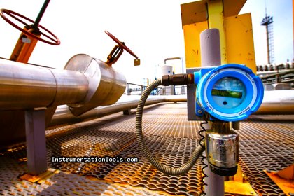
Study about the Hydrogen Sulfide (H2S) Gas Detector Calibration Procedure with zero and span gas testing.

Last updated: May 8, 2025 4:37 pm
Editorial Staff
Calibration Fire & Gas System
No Comments
Share
4 Min Read
SHARE

Study about the Infrared Hydrocarbon (H2S) Gas Detector Calibration Procedure with zero and span gas testing.

Contents
Hydrogen Sulfide Gas Detector CalibrationZero CalibrationSpan CalibrationReturning to Normal Operation

Hydrogen Sulfide Gas Detector Calibration

Hydrogen Sulfide Gas Detector Calibration Procedure

Before starting the job, take the proper work permit and inform to all the respective departments. Also do force the respective logics or interlocks if any.

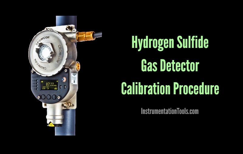
The below calibration procedure explained for crowcon make H2S gas detectors.

  • Open the Gas Detector’s cover cap by rotating it anticlockwise.
  • Check the Display which is located internally on gas detector, this display’s digits to be shown on clean atmospheric condition is “000 PPM”.
  • Check the +24 Volts DC Supply between + and – terminal of the Gas Detector.

Zero Calibration

For Zeroing the H2S Gas Detector, following procedure should be proceed:

  • Place the end of “CRO – Mag” magnet over the Menu key of the detector.
  • Green status LED will flash. Decimal point above ‘ZERO’ will illuminate.
  • Display backlight wills illuminate.
  • Decimal point above ‘INHIBIT’ may flash if the option has been internally selected.
  • With no flammable gas present at the detector place the end of ‘CRO – mag’ key over the “UP” or “DOWN” arrow pads to make the display read zero.

Span Calibration

For Calibrating the H2S Gas Detector, following procedure should be proceed:

  • Place the end of “CRO – Mag” magnet over the Menu pad.
  • The decimal point above the word “CAL” will illuminate. Other indications remain unchanged.
  • Apply the calibration gas to the detector at the flow rate of 0.5 LPM.
  • Allow the reading to stabilize.
  • Place the end of “CRO – Mag” over the “UP” or “DOWN” arrow pads to make the display read the correct concentration.
  • If the control equipment display requires adjustments consult the operating manual for the equipment.

Returning to Normal Operation

  • Place the end of “CRO – Mag” magnet over the Menu pad.
  • All decimal points will disappear and the backlight will turn off.
  • The green status LED will be on steady. (Assuming no gas present in the detector)
  • The detector is now operational.
  • Notedown the alarm tag and descriptions from the HMI or workstation. The alarm details must match with the H2S gas detector tag number and installed location.
  • Confirm the H2S gas detector activation status from the respective graphics page. You have to visually identify the color change signals of the respective H2S gas detector on the graphics.
  • Repeat the above procedure for all the remaining H2S gas detectors.
  • Normalize the forced interlocks or logics if any.
  • Close the work permit.

Note: The mentioned voltages, terminals, circuit module names may vary as per the vendor or model of the Hydrogen Sulfide Gas Detector.

Author: V Hemanth

Read Next:

  • Fire Water Sprinklers
  • Importance of Fire System
  • End of Line (EOL) Resistor
  • Fire System Loop Check
  • Smoke Detector Testing

Don't Miss Our Updates
Be the first to get exclusive content straight to your email.
We promise not to spam you. You can unsubscribe at any time.
Invalid email address
You've successfully subscribed !

Continue Reading

Installation and Calibration of Level Transmitter
Smart Transmitter Calibration Tutorial Part 2
Deluge System for Transformer Protection Animation
Practical Calibration Standards
Argonite/CO2 Flooding System Master & Slave Cylinder Operation
Deluge Valve Operation
Share This Article
Facebook Whatsapp Whatsapp LinkedIn Copy Link
Share
Leave a Comment

Leave a Reply Cancel reply

Your email address will not be published. Required fields are marked *

Stay Connected

128.3kFollowersLike
69.1kFollowersFollow
210kSubscribersSubscribe
38kFollowersFollow

Categories

Explore More

DP Transmitter Interface Level Measurement Principle, Limitations, Selection, Installation, Design & Calibration
Error sources creating uncertainty in Calibration
Instrument Turndown Ratio
Solenoid Valve Functional Testing
Pressure Transmitter Calibration at the bench
Calibration of Pyrometers using Black Body
Pressure Transmitter Calibration Procedure
Step by Step Guide for Gas Flow Meter Calibration

Keep Learning

Catalytic Gas Sensor Working

Catalytic Type Gas Sensor Principle

Pressure Safety Valve Leak Test Procedure

Pressure Safety Valve Leak Test Procedure (PSV Testing)

Reliability Centered Maintenance (RCM)

What is Reliability Centered Maintenance? (RCM)

Magnetostrictive Level Transmitter Calibration

Magnetostrictive Level Transmitter Calibration Procedure

Closed tank DP Level Transmitter with wet leg elevation zero remote mount Calibration

Closed tank DP Level Transmitter with wet leg elevation zero remote mount Calibration

Gas Detectors Calibration

Calibration of Gas Detectors

Fieldbus Flow Transmitter Calibration

Foundation Fieldbus Transmitter Calibration

DeadWeight Tester

DeadWeight Tester Questions

Learn More

ATEX Standards

ATEX Standards

Protection Relays Interview Questions & Answers

Protection Relays Interview Questions & Answers

Parallel Circuit

Parallel Circuit

Ladder Logic for Flow Meter Totalizer

Ladder Logic for Flow Meter Totalizer

Cold Email Deliverability

Cold Email Deliverability – Latest Comprehensive Guide

Moisture Separator

Inhouse Moisture separator for Pneumatic Systems

Mass Flow Calculations of flow measurement

Mass Flow Calculations

If Else Statement in SCL Language

If Else Statement in SCL Language

Menu

  • About
  • Privacy Policy
  • Copyright

Quick Links

  • Learn PLC
  • Helping Hand
  • Part Time Job

YouTube Subscribe

Follow US
All rights reserved. Reproduction in whole or in part without written permission is prohibited.
Welcome Back!

Sign in to your account

Username or Email Address
Password

Lost your password?