Inst ToolsInst ToolsInst Tools
  • Courses
  • Automation
    • PLC
    • Control System
    • Safety System
    • Communication
    • Fire & Gas System
  • Instrumentation
    • Design
    • Pressure
    • Temperature
    • Flow
    • Level
    • Vibration
    • Analyzer
    • Control Valve
    • Switch
    • Calibration
    • Erection & Commissioning
  • Interview
    • Instrumentation
    • Electrical
    • Electronics
    • Practical
  • Q&A
    • Instrumentation
    • Control System
    • Electrical
    • Electronics
    • Analog Electronics
    • Digital Electronics
    • Power Electronics
    • Microprocessor
  • Request
Search
  • Books
  • Software
  • Projects
  • Process
  • Tools
  • Basics
  • Formula
  • Power Plant
  • Root Cause Analysis
  • Electrical Basics
  • Animation
  • Standards
  • 4-20 mA Course
  • Siemens PLC Course
Reading: How Valve Positioners act as Cascade Control Systems in a Loop?
Share
Font ResizerAa
Inst ToolsInst Tools
Font ResizerAa
  • Courses
  • Design
  • PLC
  • Interview
  • Control System
Search
  • Courses
  • Automation
    • PLC
    • Control System
    • Safety System
    • Communication
    • Fire & Gas System
  • Instrumentation
    • Design
    • Pressure
    • Temperature
    • Flow
    • Level
    • Vibration
    • Analyzer
    • Control Valve
    • Switch
    • Calibration
    • Erection & Commissioning
  • Interview
    • Instrumentation
    • Electrical
    • Electronics
    • Practical
  • Q&A
    • Instrumentation
    • Control System
    • Electrical
    • Electronics
    • Analog Electronics
    • Digital Electronics
    • Power Electronics
    • Microprocessor
  • Request
Follow US
All rights reserved. Reproduction in whole or in part without written permission is prohibited.
Inst Tools > Blog > Control Systems > How Valve Positioners act as Cascade Control Systems in a Loop?

How Valve Positioners act as Cascade Control Systems in a Loop?

Last updated: November 4, 2020 12:52 pm
Editorial Staff
Control Systems Control Valves
No Comments
Share
2 Min Read
SHARE

Explain how all valve positioners essentially act as cascade control systems in a loop, and why valve positioners generally improve control quality as a result.
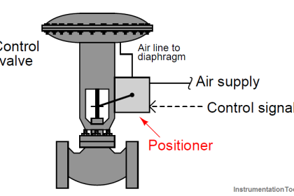
Valve Positioners

How Valve Positioners act as Cascade Control Systems in a Loop?

Furthermore, examine this block diagram of an electronic (“smart”) valve positioner and comment on its own internal “control strategy” for achieving optimum positioning:

Answer:

Electronic valve positioners act as controllers of a sort by sensing stem position (PV), comparing that PV against the command value coming from the loop controller (the positioner’s SP), and finally generating its own pneumatic output signal to drive the actuator and move the valve to where it should be.

A potential problem with electronic positioners is the potential to mis-tune its internal control(lers), resulting in oscillations if the internal control is too aggressive and sluggishness if the internal control is not aggressive enough.

Read Next:

  • Pneumatic Valve Positioner
  • Control Valves Pre-Commissioning
  • How to Select a Control Valve?
  • Control Valve Calibration
  • Types of Valve Characteristics

Questions for you:

1. Comment on the “+” and “−” symbols shown in this diagram. Based on these symbols, determine the control action (direct or reverse) for each of the controllers.

2. Certainly, modern “smart” valve positioners promise superior control valve performance than mechanical valve positioners did. Can you think of any potential disadvantages of a smart valve positioner, especially after examining the block diagram in detail?

3. How exactly does a “smart” positioner sense the valve stem’s position?

4. For those who have studied control valve positioners, identify some of the special features offered by a “smart” positioner.

5. Predict the effect(s) of the nozzle plugging inside the positioner’s relay.

6. Predict the effect(s) of the travel sensor failing with a 0% (fully-closed) signal.

7. Predict the effect(s) of the pressure sensor failing with a 100% (full-pressure) signal.

Join the Discussion! Share your answers with us through below comments section.

Don't Miss Our Updates
Be the first to get exclusive content straight to your email.
We promise not to spam you. You can unsubscribe at any time.
Invalid email address
You've successfully subscribed !

Continue Reading

What is DeviceNet?
What is Mixing or Diverting Valve ?
Control Valve Fail Safe Action
Control Loops Objective Questions and Answers
14 Basic Control Systems Questions for Interview Preparation
Problem in Water Level Control System
Share This Article
Facebook Whatsapp Whatsapp LinkedIn Copy Link
Share
Leave a Comment

Leave a Reply Cancel reply

Your email address will not be published. Required fields are marked *

Stay Connected

128.3kFollowersLike
69.1kFollowersFollow
210kSubscribersSubscribe
38kFollowersFollow

Categories

Explore More

Stroke Checking Procedure for GCV, SRV, IGV, and LFBV
How Pilot operated Solenoid Valve Works ?
PID Controller Parameters Tuning Manually
Metal Seated Valves and Soft Seated Valves : Differences
What is Process Control?
Electronic Valve positioners
Difference between Fieldbus, Profibus and HART Protocols
What is Valve Packing ?

Keep Learning

Loop Calibrator to Simulate a 4-20 mA Signal

Loop Calibrator to Simulate a 4-20 mA Signal

Electrical Drives Animation

Electrical Drives – Modes, Types, Speed Control Applications

What is Loop Checking

What is Loop Checking?

On-Off Valve Problems

How to Solve On-Off Valve Problems?

Instrumentation Cyber Security Tips

How to Stop Cyber Attacks on PLC or DCS?

Industrial Networking Interview Questions

Industrial Networking and Wireless Interview Questions

What is a Spool valve

What is a Spool Valve? – Types, Configurations, Applications

Signal Isolator

What is a Signal Isolator? Principle, Advantages, Disadvantages

Learn More

What is Photoionization Detector (PID)

What is Photoionization Detector (PID)?

BJT Amplifiers Interview Questions & Answers

BJT Amplifiers Interview Questions & Answers

HMI configuration for Delta VFD

Modbus Communication between Delta PLC with VFD

SCL Language in Siemens Tia Portal

FOR DO Statement in SCL Language

Control Valve pressure recovery

What is Control Valve Flashing ?

What is a Core Type Transformer

Difference Between Core and Shell Transformers

How to Install a Rotameter

How to Install a Rotameter

FMCW Radar level transmitter Working Principle

FMCW Radar Level Transmitter Working Principle

Menu

  • About
  • Privacy Policy
  • Copyright

Quick Links

  • Learn PLC
  • Helping Hand
  • Part Time Job

YouTube Subscribe

Follow US
All rights reserved. Reproduction in whole or in part without written permission is prohibited.
Welcome Back!

Sign in to your account

Username or Email Address
Password

Lost your password?