Inst ToolsInst ToolsInst Tools
  • Courses
  • Automation
    • PLC
    • Control System
    • Safety System
    • Communication
    • Fire & Gas System
  • Instrumentation
    • Design
    • Pressure
    • Temperature
    • Flow
    • Level
    • Vibration
    • Analyzer
    • Control Valve
    • Switch
    • Calibration
    • Erection & Commissioning
  • Interview
    • Instrumentation
    • Electrical
    • Electronics
    • Practical
  • Q&A
    • Instrumentation
    • Control System
    • Electrical
    • Electronics
    • Analog Electronics
    • Digital Electronics
    • Power Electronics
    • Microprocessor
  • Request
Search
  • Books
  • Software
  • Projects
  • Process
  • Tools
  • Basics
  • Formula
  • Power Plant
  • Root Cause Analysis
  • Electrical Basics
  • Animation
  • Standards
  • 4-20 mA Course
  • Siemens PLC Course
Reading: How to Select a Pneumatic Manifold
Share
Font ResizerAa
Inst ToolsInst Tools
Font ResizerAa
  • Courses
  • Design
  • PLC
  • Interview
  • Control System
Search
  • Courses
  • Automation
    • PLC
    • Control System
    • Safety System
    • Communication
    • Fire & Gas System
  • Instrumentation
    • Design
    • Pressure
    • Temperature
    • Flow
    • Level
    • Vibration
    • Analyzer
    • Control Valve
    • Switch
    • Calibration
    • Erection & Commissioning
  • Interview
    • Instrumentation
    • Electrical
    • Electronics
    • Practical
  • Q&A
    • Instrumentation
    • Control System
    • Electrical
    • Electronics
    • Analog Electronics
    • Digital Electronics
    • Power Electronics
    • Microprocessor
  • Request
Follow US
All rights reserved. Reproduction in whole or in part without written permission is prohibited.
Inst Tools > Blog > Instrumentation Design > How to Select a Pneumatic Manifold

How to Select a Pneumatic Manifold

Last updated: April 21, 2019 6:01 pm
Editorial Staff
Instrumentation Design
No Comments
Share
2 Min Read
SHARE

Consider These 6 Elements When Selecting A Pneumatic Manifold

Manifolds provide a convenient junction point for the distribution of fluids or gases.  Quickly thread fittings or valves into the ports to produce an organized method of supplying multiple lines from a single source.  Although simple in design, there are several elements that must be considered when selecting a manifold for your application.

Selecting A Pneumatic Manifold

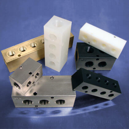
1.  Material – Pneumatic manifolds are manufactured from a variety of metals and plastics, therefore, it is important to know what material is compatible with the media in your application.  Selecting an incompatible material can cause corrosion of the manifold resulting in leakage at the distribution point in your system.

2.  Port Size – Manifolds feature a variety of input and output porting options to accommodate the control valves and fittings required in an application.  When designing your fluid control circuit, be sure to select components with the same thread size to speed installation in the manifold’s output ports.

3.  Number of Stations – How many lines will be connected at your distribution point?  Most standard manifolds have two to 10-stations, however, custom manifolds can be manufactured to accommodate the number of components required in your circuit.

4.  Spacing – One of the most commonly forgotten elements of manifold selection is the spacing between the manifold’s output ports.  When selecting a manifold, you want to ensure that the control valves or fittings can be installed without interfering with a neighboring component.

5.  Operating Pressure – Different materials have different pressure limitations.  Be sure to review the operating pressures published by the manufacturer to ensure that the manifold won’t rupture when used in your application.

6. Placement – Consider where the manifold is going to be placed within your system.  The closer the manifold assembly is to your equipment, the fewer long lines that will need to be run, saving money and providing plumbing convenience.

Also Read: Control Valve Characteristics

Don't Miss Our Updates
Be the first to get exclusive content straight to your email.
We promise not to spam you. You can unsubscribe at any time.
Invalid email address
You've successfully subscribed !

Continue Reading

Why is Orifice Beta in between 0.3 to 0.7?
Purpose of Loop Diagrams
When to use a Diaphragm Seal?
Process Control Systems Philosophy Concept
Testing of Pneumatic Systems
Failsafe Wiring Practices
Share This Article
Facebook Whatsapp Whatsapp LinkedIn Copy Link
Share
Leave a Comment

Leave a Reply Cancel reply

Your email address will not be published. Required fields are marked *

Stay Connected

128.3kFollowersLike
69.1kFollowersFollow
210kSubscribersSubscribe
38kFollowersFollow

Categories

Explore More

Zener Diode Voltage Regulators
Explain Operation of the Lamp Circuit ?
Compliance Table Application (for Procurement Service Cycle)
How to Select the Right Panel Enclosure for Your Application?
Thermowell Outer Diameter Larger than Nozzle Inside Diameter?
Troubleshooting a Power Supply Circuit
Why Orifice Flow Meter Flange is Not Recommended 150# Rating?
Signal Coupling and Cable Separation

Keep Learning

Instrument Air Quality

Instrument Air Quality

Thermowell Immersion Length

Thermowell Insertion and Immersion Length

Load Cell Design

How to select a load cell?

Relay Circuit for Hooter with Reset Button

Relay Latching Circuit using Push Button

Control Loop

What is a Control Loop ?

Differential Pressure Transmitters Static Pressure

What is Static Pressure Limit in DP Transmitter ?

plc-analog-signals-wiring-techniques

PLC Analog Signals Wiring Techniques

Instrumentation Cable trays in Horizontal Installation

Instrumentation Cable trays Installation in vertical orientation

Learn More

Power Electronics Objective Questions

PWM Inverter Quiz

Measurement of Voltage Objective Questions

Measurement of Voltage Objective Questions

MCQ on PLC (Programmable Logic Controller)

MCQ on PLC (Programmable Logic Controller)

How to Use Loop Calibrator

Troubleshooting with Loop Calibrator

How to Train Your Maintenance Team for Industrial Automation Systems

How to Train Your Maintenance Team for Industrial Automation Systems?

Turbine Meter in Gas Metering System

Read Gas Composition from Gas Metering System using RS485 Protocol

PLC Code to Start & Stop Motor and Pump as per Logic

PLC Code to Start & Stop Motor and Pump as per Logic

VFD Commissioning and Testing Procedure

VFD Commissioning and Testing Procedure (Variable Frequency Drive)

Menu

  • About
  • Privacy Policy
  • Copyright

Quick Links

  • Learn PLC
  • Helping Hand
  • Part Time Job

YouTube Subscribe

Follow US
All rights reserved. Reproduction in whole or in part without written permission is prohibited.
Welcome Back!

Sign in to your account

Username or Email Address
Password

Lost your password?