Inst ToolsInst ToolsInst Tools
  • Courses
  • Automation
    • PLC
    • Control System
    • Safety System
    • Communication
    • Fire & Gas System
  • Instrumentation
    • Design
    • Pressure
    • Temperature
    • Flow
    • Level
    • Vibration
    • Analyzer
    • Control Valve
    • Switch
    • Calibration
    • Erection & Commissioning
  • Interview
    • Instrumentation
    • Electrical
    • Electronics
    • Practical
  • Q&A
    • Instrumentation
    • Control System
    • Electrical
    • Electronics
    • Analog Electronics
    • Digital Electronics
    • Power Electronics
    • Microprocessor
  • Request
Search
  • Books
  • Software
  • Projects
  • Process
  • Tools
  • Basics
  • Formula
  • Power Plant
  • Root Cause Analysis
  • Electrical Basics
  • Animation
  • Standards
  • 4-20 mA Course
  • Siemens PLC Course
Reading: How to Prevent Ground Loops in Analog Circuits?
Share
Font ResizerAa
Inst ToolsInst Tools
Font ResizerAa
  • Courses
  • Design
  • PLC
  • Interview
  • Control System
Search
  • Courses
  • Automation
    • PLC
    • Control System
    • Safety System
    • Communication
    • Fire & Gas System
  • Instrumentation
    • Design
    • Pressure
    • Temperature
    • Flow
    • Level
    • Vibration
    • Analyzer
    • Control Valve
    • Switch
    • Calibration
    • Erection & Commissioning
  • Interview
    • Instrumentation
    • Electrical
    • Electronics
    • Practical
  • Q&A
    • Instrumentation
    • Control System
    • Electrical
    • Electronics
    • Analog Electronics
    • Digital Electronics
    • Power Electronics
    • Microprocessor
  • Request
Follow US
All rights reserved. Reproduction in whole or in part without written permission is prohibited.
Inst Tools > Blog > Control Systems > How to Prevent Ground Loops in Analog Circuits?

How to Prevent Ground Loops in Analog Circuits?

In this post, we will see what a ground loop is in an analog circuit and how to prevent ground loops.

Last updated: October 17, 2023 3:18 pm
Viral Nagda
Control Systems PLC Tutorials
No Comments
Share
7 Min Read
SHARE

In this post, we will see what a ground loop is in an analog circuit and how to avoid it.

Contents
How Current Flows in an Analog Circuit?Transmitter LoopShielded WiresGround LoopCauses of Ground LoopHow to Prevent Ground Loops?

The two most used types of analog signals in instrumentation are 0-10 V and 4-20 mA. Of these, the widely popular one that is used is the 4-20 mA type one.

The most important advantage of the current signal over-voltage signal is wiring. A voltage transmitter will mostly require a 4-wire connection.

But, a current transmitter can be configured with only 2 wires in connection. Current transmitters are less prone to electromagnetic interference.

Also, if the distances are long for connection, resistances increase with distance which causes a larger voltage drop. This problem does not occur in current transmitters.

How Current Flows in an Analog Circuit?

Now, let us understand first how a current loop flows in an analog circuit by simple Ohm’s law. Refer to the below image.

The circuit consists of a power supply and two loads (R1 & R2).

How a current loop flows in an analog circuit

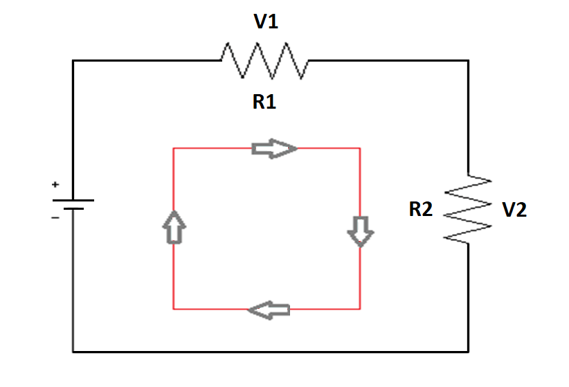
The power supply will give the voltage required to drive the current loop. Through current passing across each load, a voltage drop occurs each of them and will vary according to the resistance available.

However, current remains the same in the whole circuit. If you remember, according to Ohm’s law, V=I*R.

Transmitter Loop

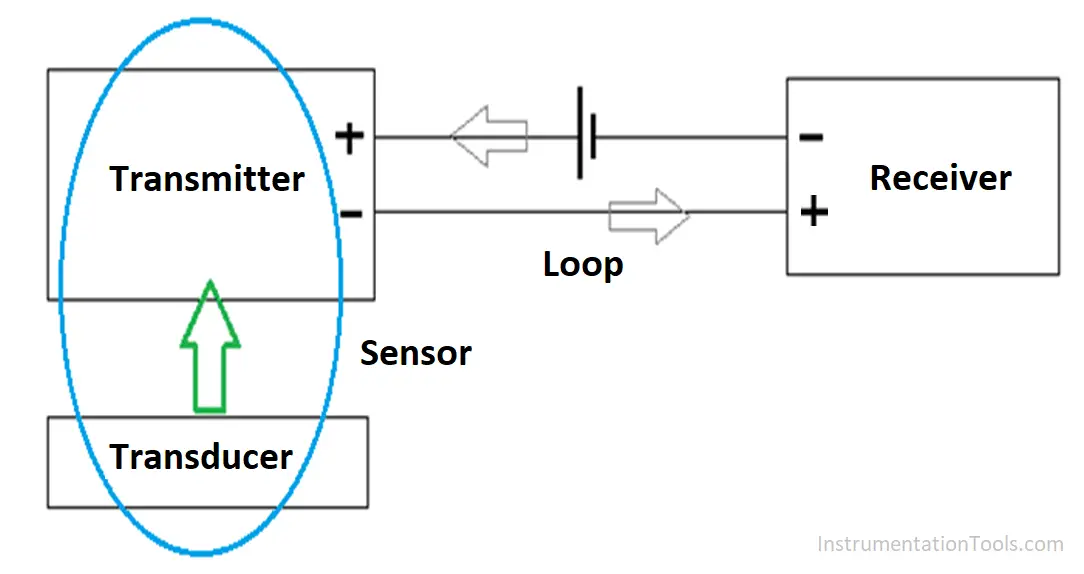
Now, let us consider the second image below. The sensor consists of a transducer and transmitter.

The transducer provides the physical signal and the transmitter converts this into an electrical signal.

A power source is used to produce the required electrical signal and drive the current in the circuit.

The loop is nothing but the wiring which carries the signal from transmitter to receiver and then back to it.
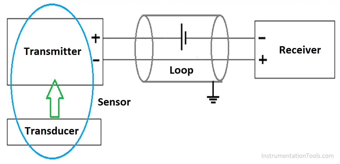
Analog Loop

Shielded Wires

Shielded wires are used mostly for analog loops. The shield side of the wire is connected to the ground to prevent noise and leakage.

And also protect the equipment terminals (sensor here) from damage. This can be understood by referring to the below image.

Shielded wires are used mostly for analog loops

Ground Loop

So, what is a ground loop? A ground loop occurs when there is more than one ground connection path between two devices. Earth potential is not the same at every point in the whole system.

Due to some designing constraints and varying load current in every path, earth potential will also vary in the loop.

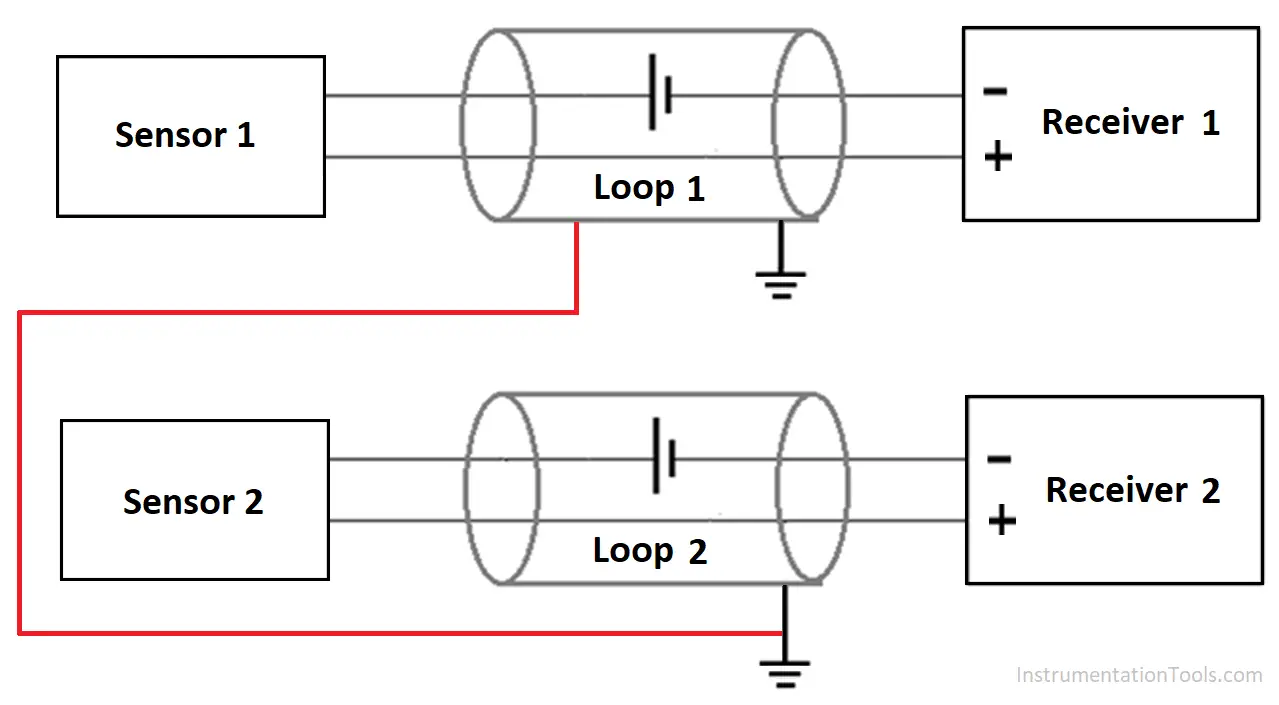
For example, if you see the below image, if the ground potential at both the points is different, then an antenna type loop current will flow between both the ground points.

Due to this, leakage current will interrupt with the proper conducting current and cause disruptions in the path.

How to Prevent Ground Loops in Analog Circuits

Causes of Ground Loop

Most common causes for ground loop are:-

  • More than one ground connection for a single loop
  • Connecting multiple devices to a single ground. Due to loopholes, current from a device can interrupt the current of other devices; causing signal fluctuations.
  • Devices with a high impedance and connected at a longer distance from the power supply.

This simply indicates that the problem will occur if there is no proper isolation between a device to ground or a device to device.

Due to this, the ground reference of the system no longer becomes stable and in opposite terms, the earthing system which we had used for protection will, in turn, become a nuisance now.

It can be like; you are providing 16 mA from PLC analog output, but the field device is functioning at 12 mA.

How to Prevent Ground Loops?

So, there are many ways to prevent a ground loop in a circuit.

Refer to the below remedies for this:

As discussed earlier, always connect a single ground to a loop. Do not connect multiple ground wires to a single loop. (Below left-side image)

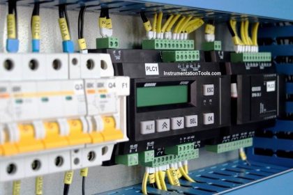
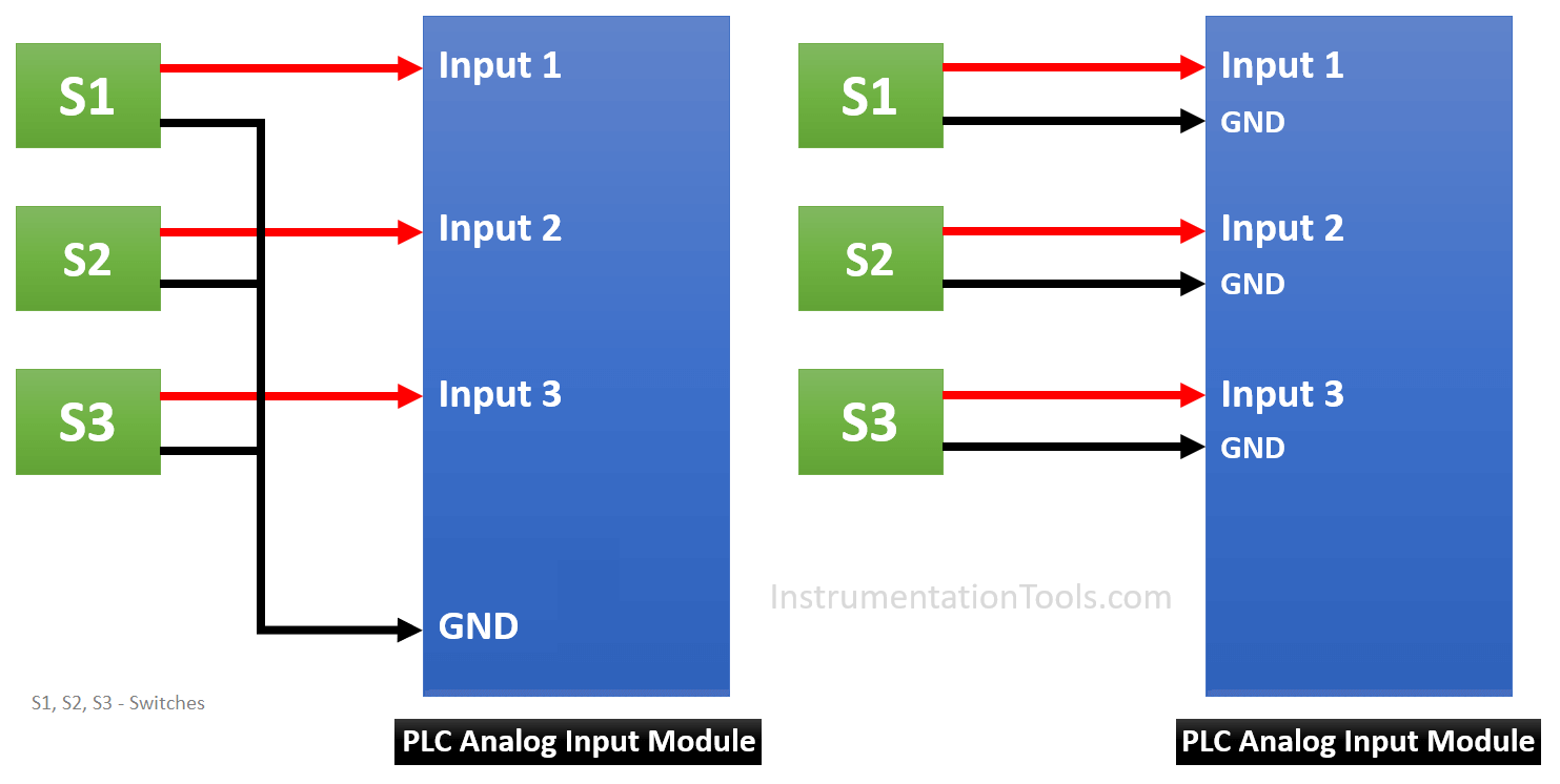
Consider the below image. If the PLC module or any other controller has multiple ground pins for corresponding inputs, that is the best solution for this remedy.

But if there is only a single common ground pin for multiple inputs, then it can cause issues or ground loop formation.

Nowadays, most of the controllers do not provide a single ground pin; there is n number of ground pins for n number of inputs. (Below right-side image)

Ground Loops in PLC

Use twisted-pair cables for reducing ground interference, as it works in cancellation theory.

Each twist acts as a small loop antenna, but after the next twist, the loop is reversed. Due to this, the interference from the second loop is cancelled by the interference from the first loop.

Use isolation between a device and the controller. The loop can be isolated by either connecting an isolator in the circuit between the sensor and controller or by using an isolated channel pin at the controller side.

Isolation is nothing but physically and electrically separating two circuits, so that there is no direct conducting path. But, data and power will still flow between each other.

The isolation only filters the proper analog signal to the channel of the controller and removes the spikes and disturbances in its input side only.

Author: Viral Nagda

If you liked this article, then please subscribe to our YouTube Channel for Instrumentation, Electrical, PLC and SCADA video tutorials.

You can also follow us on Facebook and Twitter to receive daily updates.

Read Next:

  • What is a SAMA Diagram?
  • Industrial Control System Book
  • Simple High-Level Indicator Circuit
  • How To Choose a Surge Protector?
  • Static and Temp Memory in TIA Portal
Don't Miss Our Updates
Be the first to get exclusive content straight to your email.
We promise not to spam you. You can unsubscribe at any time.
Invalid email address
You've successfully subscribed !

Continue Reading

Product Sticker Machine with Weighing PLC Program
How to Communicate with Excel from Intouch SCADA?
PLC Project: Detect Overweight and Less Weight Bottles
Cloud-Based SCADA Projects – Try Free Demo Account
PLC Multiple Choice Questions
Basics of Fail-safe Circuits
Share This Article
Facebook Whatsapp Whatsapp LinkedIn Copy Link
Share
Leave a Comment

Leave a Reply Cancel reply

Your email address will not be published. Required fields are marked *

Stay Connected

128.3kFollowersLike
69.1kFollowersFollow
210kSubscribersSubscribe
38kFollowersFollow

Categories

Explore More

Create a User-Defined Function Block in Codesys
Download Free HMI software – CODESYS
Difference Between PNP and NPN Sensors
Electrical Switches Principle & Types
Tuning a Temperature Process Control Loop
Free Allen Bradley PLC Ladder Logic Training Course
What is DIN rail ?
Retentive ON Delay Timer using PLC

Keep Learning

PLC Power Supply and Operating Voltages

PLC Power Supply and Operating Voltages

DeviceNet

What is DeviceNet?

Level Transmitter configuration in PLC

Scaling with Parameters (SCP) Instruction in PLC

PLC Stop - Start Circuit

Introduction to PLC Ladder Diagrams

Grounding Electronic Equipment

Importance of Grounding Electronic Equipment

PLC Programming in Hindi - Siemens Tia Portal Full Course

PLC Programming in Hindi – Siemens Tia Portal Full Course Free

PLC Program for an Alternate output circuit

PLC Program for Alternate Output Circuit with Latched Function

PLC-Complete-Training-Package

Free PLC Training Software Download

Learn More

Differential Pressure (DP) Flow Meters Range Calculation Methods

Differential Pressure (DP) Flow Meters Range Calculation Methods

Top 100 PLC Objective Questions and Answers

Top 100 PLC Objective Questions and Answers

TIA Portal MOVE Instruction

MOVE Instruction in PLC – What You Need to Know?

Orifice plate with vent and drain holes

Basics of Orifice Plates

Digital Electronics Multiple Choice Questions

Magnitude Comparator Objective Questions

Steam Turbine Driven Centrifugal Compressors Leak due to Broken Instrument

Steam Turbine Driven Centrifugal Compressors Leak due to Broken Instrument

Thermocouple Law of Intermediate Metals

Thermocouples Law of Intermediate Metals

Input function blocks

FF Function Blocks

Menu

  • About
  • Privacy Policy
  • Copyright

Quick Links

  • Learn PLC
  • Helping Hand
  • Part Time Job

YouTube Subscribe

Follow US
All rights reserved. Reproduction in whole or in part without written permission is prohibited.
Welcome Back!

Sign in to your account

Username or Email Address
Password

Lost your password?