In this article, you will learn how to full up instrument datasheet, pressure gauge specifications and their standards.
How to Fill up Instrument Datasheet?
Step 1: Datasheet Format. Freeze the final format of the datasheet.
e.g. ISA20, Instrument Specification Forms/ Client format / Vendor format etc
Generally, the datasheet format covers the document number, title, client logo, project name, project number, revision history table, etc since every project is unique, and this document is used for the entire life cycle of the project until the plant is decommissioned.
When you look at the format of the datasheet, you will notice/realize that datasheet is sub-divided into various sections like General data, process-specific data, material / mechanical specific data, instrument-specific data, notes/ remark section, testing and inspection data, certification & standards related information, special requirements and purchasing data.
The most important thing for instrument selection is that it should be “fit for purpose”.
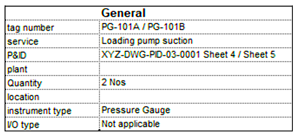
Step 2: General data
To fill up the general section, we need to fill in the tag number and other general information.
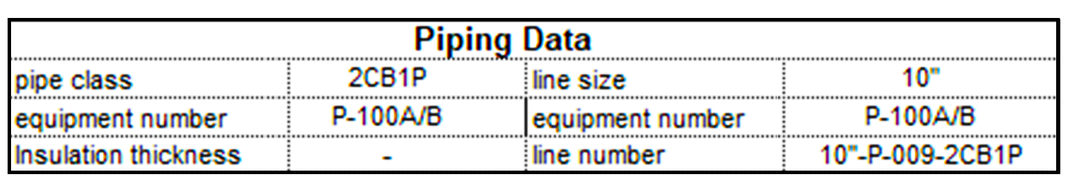
From the P&ID (Piping and instrumentation diagram), one can get the instrument tag number, line number & line size/equipment number, PMS (piping material specification) and service, etc
Step 3: Get the process data [This is the interface between the process and instrument engineer]
Normally process engineers provide the process data applicable for the instrument in form of an instrument process datasheet which is also called IPDS.
Process engineers provide this information based on Material & heat balance streams. Sometimes this being an interface document, the format of IPDS is aligned with the Instrument datasheet process data section.
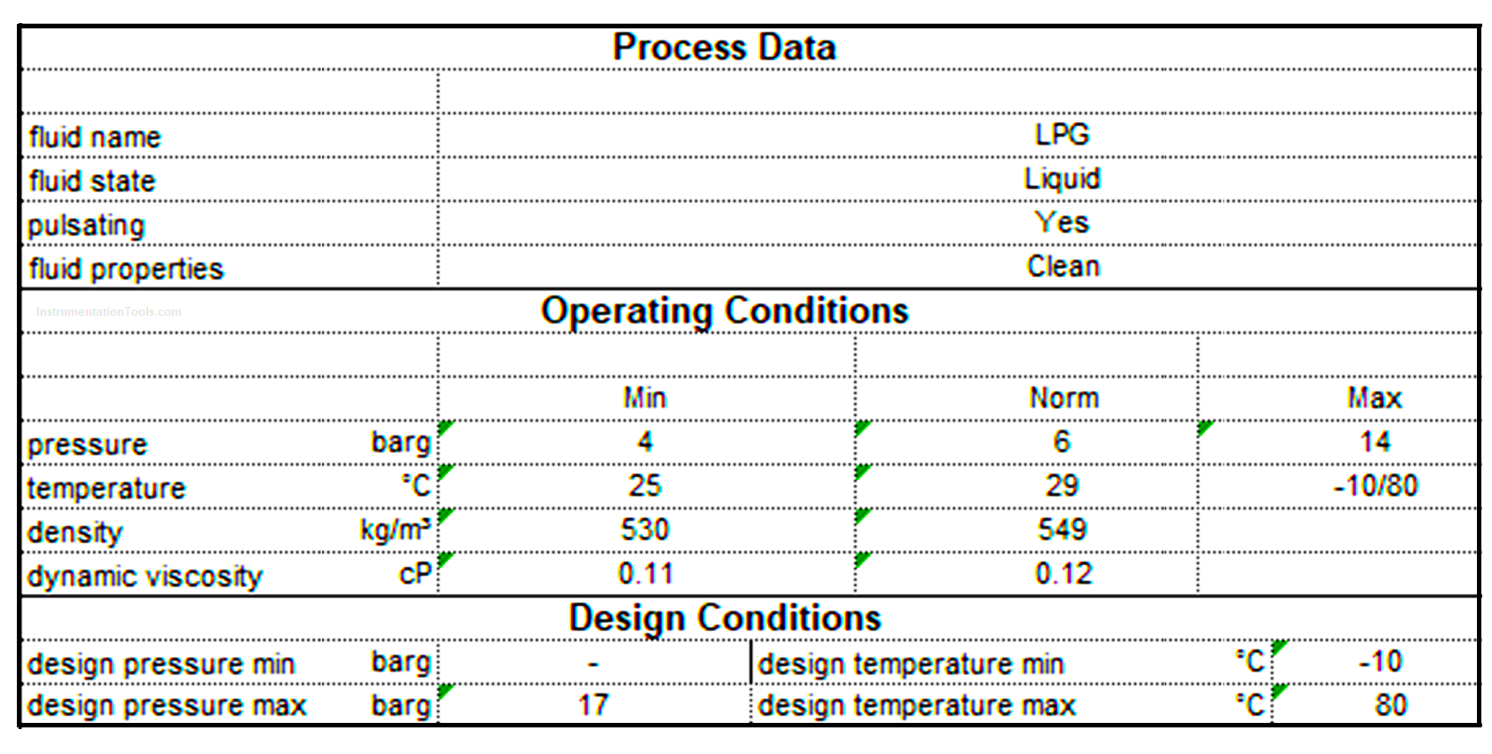
IPDS covers fluid name, its state (Gas / Liquid / solid) and properties like corrosive / toxic / erosive
It will also cover operating conditions (minimum, normal, maximum) and design conditions of the process that is applicable for a particular instrument. Here in this example pressure gauge.
As we know for pressure measurement, the pressure of operating & design conditions is important. In general, for all IPDS pressure and temperature of the process are given.
Design conditions are something that the instrument may experience at very low intervals or may not experience at all. The low interval could be the startup of a plant, or shut down of the plant.
Note: It’s not advisable to collect the process data and blindly follow in instrument datasheet.
Sometimes you may notice different process data for different instruments on the same line.
In case of strange data, you may consult your process depart and get clarity before you proceed.
There could be a problem with unit conversion, and decimal separation.
Care must be taken when you import process raw data into automated instrument datasheet tools.
Step 4: Get the mechanical/material/piping data
We normally follow piping material specification documents for specifying material required for instrumentation items. The logic for the same is simple, fluid will pass through all piping components and so it is applicable for instruments mounted on/connected to the pipe. Generally, the material of construction and end connection rating shall be as per piping material specification.
The above section is more important for Control valves, on-off valves, and inline flowmeters. For other instruments sometimes project requirement calls for minimum SS316 material wetted part unless otherwise specified or better as required by PMS.
The pressure gauge sensing element shall be of SS316 as a minimum or better as required by PMS.
e.g. if the piping material is HASTELLOY C276 [one of the few alloys resistant to wet chloride gas, hypochlorite, and chlorine dioxide solutions] then the minimum case of SS316 would not be a good choice. Remember instrument material selection is also fit for purpose and suitable for specified service.
Step 5: Get the specific requirement for the instrument. Here it is important to know your project-specific requirement.
It is very important that we should understand the part list of instruments and specify the requirement for the instrument. Vendor catalogs, videos, literature, whitepaper, Installation, and operating manual are important sources to gather important & trending information.
Examples of Pressure Gauge Specification
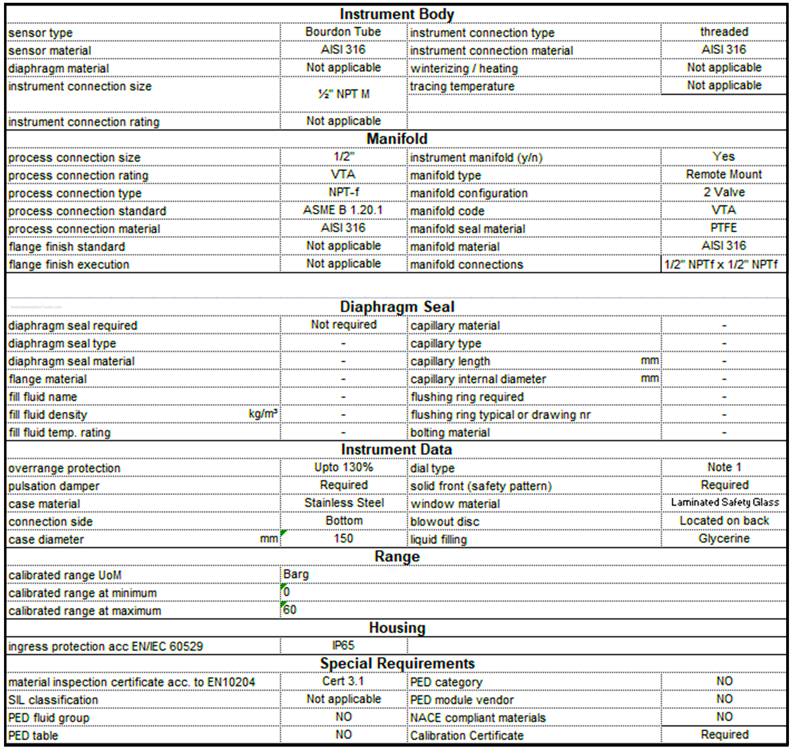
- The pressure element shall be bourdon, diaphragm, or bellows depending upon process condition. Generally, for positive pressure bourdon type gauge is the first choice.
- The pressure gauge dial shall be white with black figures & dial size of 150 mm. The dial shall be marked with pressure element material. The connection shall be 1/2″ NPTM bottom. The normal Operating Pressure range on the dial shall be of Green color.
- Pressure gauges shall have an accuracy of ±1% of Full scale.
- The pressure gauge shall be with external zero adjustment features.
- Pressure gauge sensing material shall be a minimum SS316 & case material shall be a minimum SS304 & with a bayonet bezel ring. Glass/window shall be shatterproof. Pointer material shall be minimum Aluminium.
- Ranges for instruments shall be selected such that in normal process operation, the indication is in between 30% to 70% of the calibration range.
- The pressure gauge shall have over-range protection of 130% of max. Operating pressure and shall have blowout disc.
- Pressure gauges with a range of more than 60 kg/cm2g shall have a solid front case.
- Remote surface mounting pressure gauges shall be considered for services of higher operating temperature than 100°C or pump discharge application.
- Instruments that can be exposed to a vacuum shall have under-range protection.
- Diaphragm seal element with capillary shall be used for toxic, congealing, corrosive, and highly viscous services. Diaphragm/flange material shall be as per process requirement, but SS316 is to be considered as a minimum. Minimum flange rating 300# & Flange size 2” for direct vessel mount diaphragm seal type.
- Where vibrations and pressure fluctuations are expected then glycerin-filled type or snubber shall be used.
- A gauge designed to indicate oxygen pressure shall comply with cleanliness level IV. The dial shall clearly indicate “USE NO OIL” in red color.
- Pressure gauge in ammonia service, materials such as copper, brass, and silver brazing alloys should not be used.
- All instruments in sour service shall meet NACE MR 0103 requirement wherever required as per piping material specification.
- Radiography, IBR testing, NACE, Post Weld Heat Treatment, and Stress relieving requirements shall be considered as per piping material specification.
- Mounting accessories as required for pressure gauge shall be of Stainless Steel.
Pressure Gauge Accessories and Attachments
- On pulsating services, pulsation dampers shall be used. Snubber is also known as a pulsation dampener. Due to pulsating pressure gauge life can be reduced. It is also difficult to read pointer reading under pulsating pressure. Snubber will suppress the line pressure pulsations and keep the pressure gauge pointer steady.
- Syphon shall be considered for pressure gauges in steam service. Syphon reduces the service temperature of process fluid entering to gauge so that measuring element exposed to the lower temperature. Condensation of the pressure medium collected inside the coiled portion of the siphon prevents direct contact with the external media.
- Pressure Limiter Valves / Gauge saver shall be used where pressure gauge needs to be prevented from overpressure. The gauge saver is used where the process pressure can exceed the over range of the Pressure Gauge. The gauge saver shuts off the pressure to the gauge in case of over range pressure and thus it prevents the damage of the sensing element of the measuring device.
- Cooling elements shall be used when the medium temperature would exceed the permissible temperature limit of the pressure measuring instrument
- Gauge adaptors shall be considered where necessary to connect instruments and accessories with different types of connection sizes/thread types. E.g. NPT and BSP threads are not compatible.
- Integral manifold / Site fabricated manifold shall be used according to project specification
Standards for Pressure Gauges
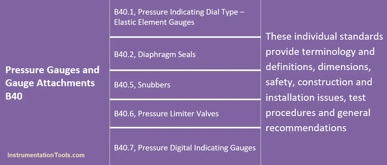
Typical pressure gauge ranges are defined in section 3.2 of B40.1, Pressure Indicating Dial Type – Elastic Element Gauges
In Table 1 of B40.1, Accuracy grades are defined as 4A, 3A, 2A, 1A, A, B, C, and D.
Grade 4A = 0.1% FS error is permissible
Grade 1A = 1% FS error is permissible
Grade D = 5% FS error is permissible
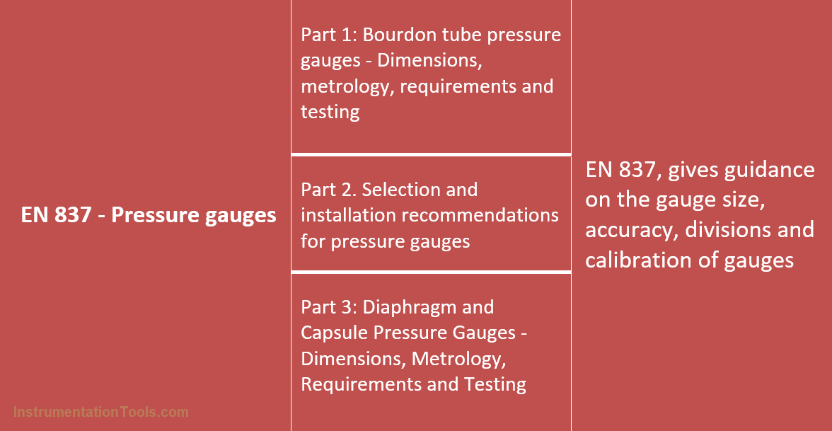
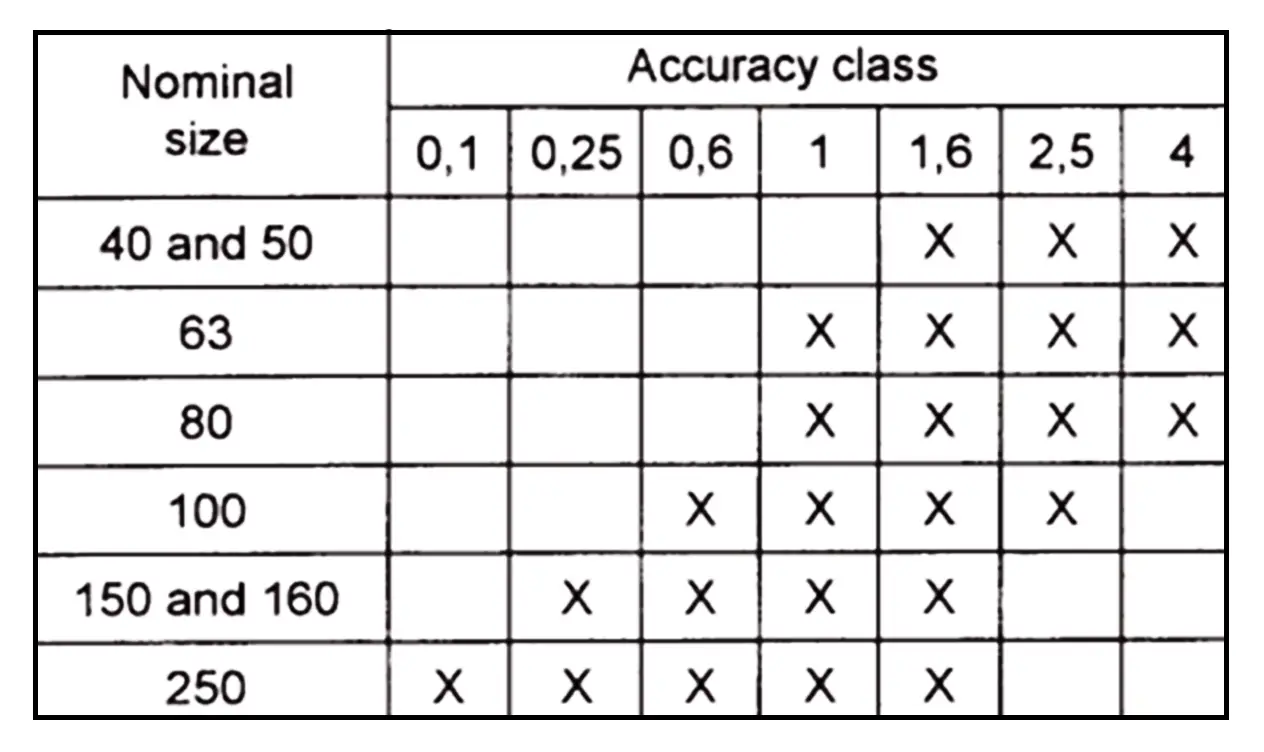
The following is a typical dial size and accuracy class defined in EN 837-1.
Generally, the cost of Pressure Gauges varies based on specification. However, to get a rough idea it is around 2500 INR to 8000 INR. The more stringent the requirement is so is the cost.
Once the pressure gauge from the approved vendor list is finalized and is fit for purpose, then the pressure gauge datasheet is revised to cover vendor supplied/offered details, make and model, and purchase requisition number.
Exercise:
If you have process data where max operating pressure is 5 Kg/cm2g and design pressure is 17 Kg/cm2g. What calibration range and accessories would you consider for the pressure gauge? Remember pressure gauge standard range as per EN 837-1 / ASME B40.1
Disclaimer: The information shared is intended only for informational & educational purposes. All content mentioned does not constitute professional advice and is not guaranteed to be accurate, complete, reliable, up-to-date, or error-free.