When choosing a control valve for a process, there are many things that must be considered, including the valve’s flow characteristic, its size, noise, the potential for cavitation or flashing damage, body and trim materials, actuator size and type, and its dynamic response to changes in the control signal.
The selection primarily depends upon the application and the pressure and temperature conditions.
There are many types of valves available, each having its advantages and limitations. The basic requirements and selection depend on their ability to perform specific functions such as:
This article discusses basic valve types, types of actuators, control actions, types of positioners.
Based on control actions, they are linear motion and rotary motion
Linear valves, also known as multi-turn valves, have a sliding-stem design that pushes a closure element into an open or closed position. Common valves are globe valves, gate valves.
Rotary motion is also known as quarter-turn valves. Quarter turn valves will be in their fully open or fully closed state (0°) after a 90° turn of the stem.
Their operation is much quicker than linear motion valves. Common are ball valves, butterfly valves.
Valves are available with a wide variety of valve bodies in various styles, materials, connections, and sizes. Selection is primarily dependent on the service conditions, the task, and the load characteristics of the application.
Read:
The most common types are ball valves, butterfly valves, globe valves, and gate valves.
Ball valves are quick opening valves that give a tight shutoff. When fully open, a ball valve creates little turbulence or resistance to flow.
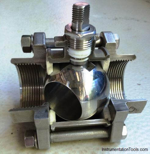
Ball valves are considered high recovery valves, having a low-pressure drop and relatively high flow capacity.
Butterfly valves consist of a disc attached to a shaft with bearings used to facilitate rotation. These are considered high recovery valves since only the disc obstructs the valve flow path. The flow capacity is relatively high and the pressure drop across the valve is relatively low.
The butterfly valves are used for limited throttling where a tight shut off is not required. When fully open, the butterfly creates little turbulence or resistance to flow.
Generally not rated as bubble-tight, and the cavities and leak paths around the disc stem are potential entrapments for fluids and slurries.
Globe valves consist of a movable disk-type element and a stationary ring seat in a generally spherical body. The valve stem moves a globe plug relative to the valve seat. The globe plug can be at any position between fully opened and fully closed to control flow through the valve.
Image Courtesy: Flowone
The globe and seat construction gives the valve good flow regulation characteristics. Turbulent flow past the seat and plug, when the valve is open, results in a relatively high-pressure drop, limited flow capacity, and low recovery.
Applications requiring: a)Precise flow regulation
Gate valves use the linear type of stem motion for the opening and closing of a valve. These valves use parallel or wedge-shaped discs as closure members that provide tight sealing.
Read:
A valve actuator is a device that produces force to open or close the valve utilizing a power source.
Two types of actuators are common:
Pneumatic actuators utilize an air signal from an external control device to create a control action via a positioner or a solenoid. These are commonly available in two main forms: piston actuators and diaphragm actuators.
Piston actuators are generally used where the stroke of a diaphragm actuator would be too short or the thrust is too small.
Diaphragm actuators have compressed air applied to a flexible membrane called the diaphragm. These types of actuators are single-acting, in that air is only supplied to one side of the diaphragm, and they can be either direct-acting (spring-to-retract) or reverse acting (spring-to-extend).
In pneumatic operated valve, there are two control actions possible:
There can also be a failure in safety modes:
Read:
The biggest advantage of pneumatic actuators is their fail-safe action. By design of the compressed spring, the engineer can determine if the valve will fail closed or open, depending on the safety of the process
Electric actuators are motor-driven devices that utilize an electrical input signal to generate a motor shaft rotation. This rotation is, in turn, translated by the unit’s linkage into a linear motion, which drives the valve stem and plug assembly for process variable modulation.
Actuators utilize two types of motors
A step motor uses gears with increments in the range of 5,000 to 10,000 at 90-degree rotation for accurate positioning at lower speeds.
Servos, by definition, are closed-loop and provide superior performance at high speeds, but at a higher cost.
Read:
A valve positioner is a control device designed to impart sensitivity to the valve and to ensure accurate positioning as dictated by a control signal.
The addition of positioner can correct many variations including changes in packing friction due to dirt, corrosion, or lack of lubrication, variations in dynamic forces of process.
A positioner may be used as a signal amplifier or booster. It accepts a low-pressure air control signal and, by using its own higher pressure input, multiplies this to provide a higher pressure output air signal to the actuator diaphragm.
When should a positioner be fitted:
A positioner should be considered in the following circumstances:
Read:
In this post, we will learn the basic requirements for a network switch to be…
The PLC panel and MCC panel interface signals are start, stop, run feedback, trip, local…
In this article, we are going to discuss about shutter door control using induction motor…
Electrical Drives control the motion of electric motors. Motion control is required in industrial and…
PLC ladder logic design to control 3 motors with toggle switch and explain the program…
VFD simulator download: Master the online tool from the Yaskawa V1000 & programming software for…


View Comments
Diapharm actuators are also double acting actuators.