Inst ToolsInst ToolsInst Tools
  • Courses
  • Automation
    • PLC
    • Control System
    • Safety System
    • Communication
    • Fire & Gas System
  • Instrumentation
    • Design
    • Pressure
    • Temperature
    • Flow
    • Level
    • Vibration
    • Analyzer
    • Control Valve
    • Switch
    • Calibration
    • Erection & Commissioning
  • Interview
    • Instrumentation
    • Electrical
    • Electronics
    • Practical
  • Q&A
    • Instrumentation
    • Control System
    • Electrical
    • Electronics
    • Analog Electronics
    • Digital Electronics
    • Power Electronics
    • Microprocessor
  • Request
Search
  • Books
  • Software
  • Projects
  • Process
  • Tools
  • Basics
  • Formula
  • Power Plant
  • Root Cause Analysis
  • Electrical Basics
  • Animation
  • Standards
  • 4-20 mA Course
  • Siemens PLC Course
Reading: How to calculate the tolerance of a RTD sensor
Share
Notification Show More
Font ResizerAa
Inst ToolsInst Tools
Font ResizerAa
  • Courses
  • Design
  • PLC
  • Interview
  • Control System
Search
  • Courses
  • Automation
    • PLC
    • Control System
    • Safety System
    • Communication
    • Fire & Gas System
  • Instrumentation
    • Design
    • Pressure
    • Temperature
    • Flow
    • Level
    • Vibration
    • Analyzer
    • Control Valve
    • Switch
    • Calibration
    • Erection & Commissioning
  • Interview
    • Instrumentation
    • Electrical
    • Electronics
    • Practical
  • Q&A
    • Instrumentation
    • Control System
    • Electrical
    • Electronics
    • Analog Electronics
    • Digital Electronics
    • Power Electronics
    • Microprocessor
  • Request
Follow US
All rights reserved. Reproduction in whole or in part without written permission is prohibited.
Inst Tools > Blog > Temperature Measurement > How to calculate the tolerance of a RTD sensor

How to calculate the tolerance of a RTD sensor

Last updated: December 22, 2018 10:25 pm
Editorial Staff
Temperature Measurement
4 Comments
Share
3 Min Read
SHARE

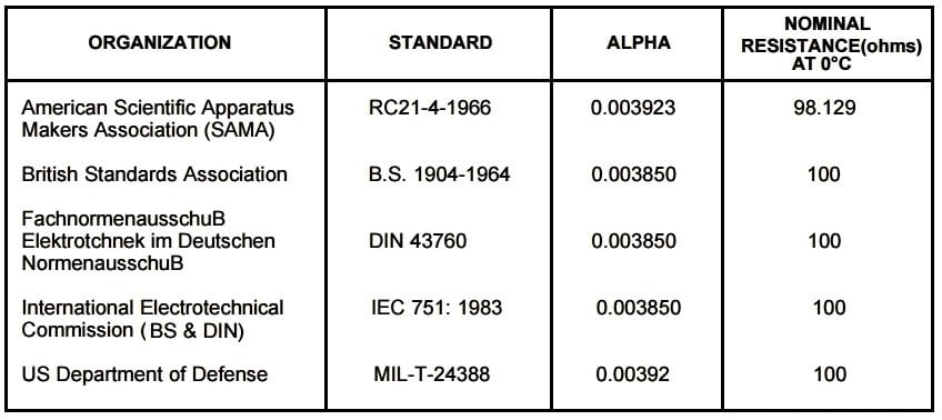
The European standard, also known as the DIN or IEC standard, is considered the world-wide standard for Pt100. This standard, DIN/IEC 60751 (or simply IEC751), requires the RTD to have an electrical resistance of 100.00 Ω at 0°C and a temperature coefficient of resistance (alpha) of 0.00385 Ω/Ω/°C between 0 and 100°C.

RTD-standards

There are actually four resistance tolerances specified in DIN/IEC751:2008

Class AA = ± ( 0.10 + 0.0017 * | t | ) °C

Class A = ± ( 0.15 + 0.0020 * | t | ) °C

Class B = ± ( 0.30 + 0.0050 * | t | ) °C

Class C = ± ( 0.60 + 0.0100 * | t | ) °C

The combination of resistance tolerance and temperature coefficient define the resistance vs. temperature characteristics for the RTD sensor. The larger the element tolerance, the more the sensor will deviate from a generalized curve, and the more variation there will be from sensor to sensor (interchangeability). This is important for users who need to change or replace sensors and want to minimize interchangeability errors.

Tolerance Testing Method

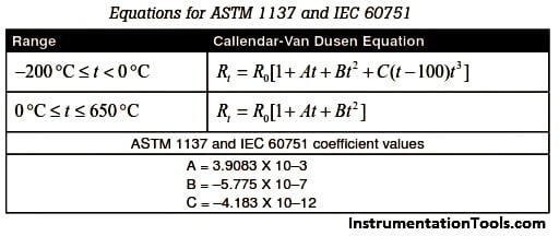
RTD calibrations involving tolerance testing are reserved for low accuracy applications. The values are defined by one of the common models such as the ASTM 1137 or IEC 60751 curve. RTDs calibrated in this way are generally used in industrial style applications

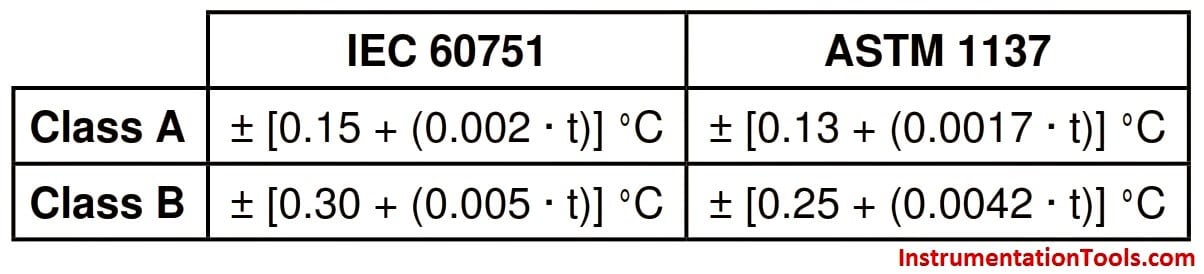
The two common accuracy classes are class A and class B:

rtd-standards-for-class-a-and-class-b

These include errors arising from deviations in R0 and from errors in slope. Frequently, we will see probes rated at a fraction of Class A.

For example, 0.1 ASTM Class A. Fractional accuracy is achievable in sensors alone, but are very difficult to achieve in probes. The calculations are straightforward.

RTD Equations for IEC60751 and ASTM 1137

Example: Calculate the accuracy of a 0.1 ASTM Class A probe at 100 °C

For ASTM standard:

Class A = ± [0.13 + (0.0017 · t)] °C
= (0.13 + (0.0017 · t)) · 0.1
= (0.13 + (0.0017 · 100)) · 0.1
= (0.13 + 0.17) · 0.1
= 0.03

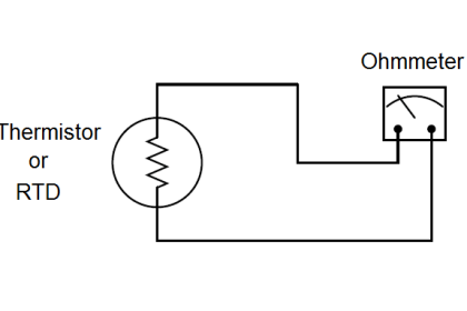
Measure the reference probe temperature = 100.0 °C

Measure the indicated temperature = 100.5 °C

Calculate the error (Difference of Indicated & Reference) = 0.05 °C

Calculate the tolerance at 100.00 °C using ASTM standard = 0.03 °C

Determine tolerance status = Fail (0.05 °C > 0.03 °C)

The above example calculates the RTD tolerance at reference and indicated temperatures and determines the tolerance status of an RTD.

Don't Miss Our Updates
Be the first to get exclusive content straight to your email.
We promise not to spam you. You can unsubscribe at any time.
Invalid email address
You've successfully subscribed !

Continue Reading

Types of Thermocouple Measuring Junction
Thermocouple Temperature Measurement Errors
Mechanical Temperature Measuring Sensors
Thermocouples Sources of Error
Temperature Coefficient of Resistance (α)
Thermocouple Calculations
Share This Article
Facebook Whatsapp Whatsapp LinkedIn Copy Link
Share
4 Comments
  • Giri says:
    May 13, 2015 at 4:06 am

    Hi,
    This is a nice explanation. Can you make a tool for RTD tolerance calculation.
    Regards,
    Giri

    Reply
    • S Bharadwaj Reddy says:
      May 14, 2015 at 6:55 am

      Hi Giri,

      Thanks for the suggestion. Soon i will post a tool on RTD tolerance.
      Thanks,
      S Bharadwaj reddy

      Reply
  • Rahul Patel says:
    January 14, 2016 at 10:12 am

    Hi Guys…!

    Its very good information we all appreciate to Mr Reddy to serve and share with us..

    Reply
  • Farakh hamayun says:
    May 14, 2024 at 10:31 pm

    Its informative thanks for sharing

    Reply

Leave a Reply Cancel reply

Your email address will not be published. Required fields are marked *

Stay Connected

128.3kFollowersLike
69.1kFollowersFollow
210kSubscribersSubscribe
38kFollowersFollow

Categories

Explore More

Thermostat – Types, Working Principle, Advantages, Applications
RTD Calibration Procedure
Important Factors for Thermocouple Selection
Thermocouple Cold Junction Compensation
Thermowell Insertion and Immersion Length
Temperature Calibration Bath Principle
Problems of Reference Junction Compensation : Thermocouples
Difference between PT100, PT1000, Nickel RTD and Balco RTD

Keep Learning

Temperature Sensors Interview Questions

Temperature Sensors Interview Questions

Thermistors and Resistance Temperature Detectors (RTDs)

Thermistors and Resistance Temperature Detectors (RTDs)

Thermocouple Calibration

Thermocouple Calibration

Temperature Switch Working

Basics of Temperature Switch

Use of Temperature Transmitters instead of Direct Wiring

Thermowell Wake Frequency Calculation

Thermowell Wake Frequency Calculation

Difference Between RTD, Thermocuples and Thermistors

Difference Between RTD, Thermocouple and Thermistor

Skin Type Thermocouple

Skin Type Thermocouple

Learn More

Move function block

Move Instruction in Tia Portal

Analyzers Questions and Answers

Infrared Gas Analyzers Questions & Answers

Difference between Absolute, Gauge and Differential Pressure Transmitters

Difference between Absolute, Gauge and Differential Pressure Transmitters

PID Controller

Proportional Integral Derivative Controllers – PID MCQ

Electrical Machines Questions and Answers

Induction Motor Rotor Frequency

Power Systems Questions & Answers

Power Systems MCQ Series 1

Selecting A Pneumatic Manifold

How to Select a Pneumatic Manifold

NPT Connections

Difference Between NPT, BSPP and BSPT Seals

Menu

  • About
  • Privacy Policy
  • Copyright

Quick Links

  • Learn PLC
  • Helping Hand
  • Part Time Job

YouTube Subscribe

Follow US
All rights reserved. Reproduction in whole or in part without written permission is prohibited.
Welcome Back!

Sign in to your account

Username or Email Address
Password

Lost your password?