Introduction to Modbus
Modbus is the “granddaddy” of industrial communication protocols. It was originally designed in the mid-1970s by Modicon as a way to link intelligent devices with PLCs using a simple master/slave concept. “Simple” is a key descriptor for Modbus – and also its biggest strength. It is easy to implement and easy to use. When it was first introduced, it was a proprietary protocol that only Modicon could use. However, it was later published royalty-free so that anyone could use it.
Finally, Modicon made it an open protocol. When it was published, a number of companies started using it, creating different interpretations and modifications of the original specification. As a result, there are now quite a few variations in the field.
The specification document is fewer than 100 pages in length, which is a good indication of the protocol’s low level of complexity. In comparison, Profibus’ specification document is thousands of pages long. The term “Modbus” typically refers to one of three related protocols: Modbus ASCII, Modbus RTU, or Modbus TCP/IP
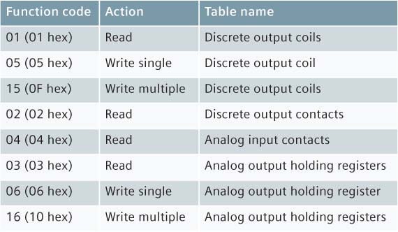
- Modbus ASCII was the first Modbus and is a serial protocol, typically running on either the RS-232 or RS-485 physical layer. All slaves are polled on demand by the master, and there is only one master. The message frame can be up to 252 bytes in length, and up to 247 addresses are possible. The message frame and function codes, shown in Figures 1 and 1.1, are very simple.
- Modbus RTU is really just a small variation on the Modbus ASCII protocol. The only difference is in the encoding of the data. ASCII encodes the message in ASCII characters, while RTU uses bytes, thus increasing the protocol’s throughput. In general, RTU is more popular, particularly in new installations.
- Modbus TCP/IP was added much later. One simple way of thinking about Modbus TCP/IP is to picture it as simply encapsulating a Modbus RTU packet within a TCP/IP packet. There is a bit more to it than that, but this is essentially what Modbus did. As a result, Modbus TCP/IP is also very simple to implement. The tradeoff is that, because it uses TCP/IP protocol for all messages, it is slow compared to other Ethernet industrial protocols – but still fast enough for monitoring applications.

How Modbus works
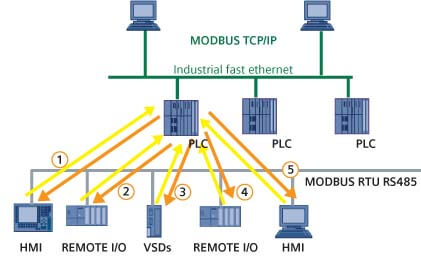
As already noted, Modbus is a simple master-slave protocol. The master has full control of communication on the bus, whereas a slave will only respond when spoken to. The master will record outputs and read in inputs from each of its slaves, during every cycle, as shown in Figure 2.
The slave devices do not “join” the network. They simply respond whenever a master talks to them. If the master never talks to them, then they are idle. There is also no requirement for diagnostics related to the slave’s health. If the master requests data that does not make sense to the slave, then the slave can send an exception response.
However, if the process variable is bad or if the device has problems functioning, there is nothing in the protocol that requires the slave to report this.
The physical layer
Modbus ASCII and RTU both typically use either the RS-232 or RS-485 physical layer, but can also use other physical layers such as phone lines or wireless. Recommended Standards (RS) 232 and 485 were established physical layers when Modbus was first developed. RS-232 is for point-to-point, while RS-485 is for multi-drop applications.
In both cases, Modbus did not add any new requirements to these physical layers. This worked, but it has caused a few problems in the case of RS-485. The problem is that the physical layer has a number of variations: 2-wire, 4-wire, use of common and variations in drivers and grounding methods.
Anyone who has worked with Modbus on RS-485 from multiple vendors will already know how to manage all the variations when connecting two types in a point-to-point configuration. The difficulty comes when the site is multi-vendor and several variations have to be combined on one cable.
There are a number of standards for both phone lines and for wireless. Modbus has excelled in these applications because of the small number of timing constraints in the protocol. Phone lines as well as wireless modems introduce delays in messages. Sometimes these delays are non-linear throughout the message, which can cause real problems for many protocols.
However, Modbus either does not have a problem with this, or it can be adapted so that it will work in these applications.
Typical applications
1. Controller/monitor to a smart device – In this application, there is one smart device from which data needs to be pulled. This point-to-point application is a common Modbus ASCII/RTU task. The variations in both the protocol and the physical layer are easy to manage, and this application is simple to get working.
2. Controller/monitor to many smart devices from the same vendor – Like the first application, this is very easy to implement. The variations in the protocol are generally not a problem.
3. Remote monitoring of information from a smart device – Since the Modbus protocol is modem-friendly.
What is Modbus ID
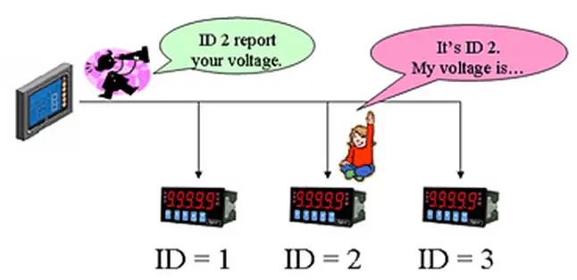
A modbus network relies on IDs of individual devices. Messages could be sent all over the network however the data is tagged from 1 to 247 (Modbus Basics restricts to addressing only 247 devices to a master).
For example in a Modbus serial network utilizing RS-485 multidrop they can daisy chain up to 31 devices in total. However each of those devices must have its own unique ID number.
Since the Modbus master is the only device to send requests to the slaves they are not assigned any ID. The communication does not exist between the slaves.
What is Modbus TCP Gateway
The Modbus TCP Gateway is the device that will bridge the gap between the Modbus TCP protocols to the traditional Modbus Serial protocols.
The gateway works like a relay device where it takes the requests from the TCP (Ethernet) side and then passes it off onto the Gateway’s serial side. Please note with this device the existing limitations such as Modbus Slaves daisy chained remains at 31 devices.






Very nice
Hello Sir!! I want to do Modbus RTU communication between field mounted controller & HMI whose Register & addresses given by both vendors.But the situation is I cant do any changes in software program of HMI (i.e. doing polling of addresses through PLC of that HMI ),So can you please help me out how it can be done ?? OR I have to give one PLC and communication module between them to read & write OR through OPC ?? If yes ,then please let me know how it can be?
There are total 13 field mounted controller which i have to connect to 13 individual HMI’s. (For set point re-transmission, PV reading Auto/Manual selection & Start /stop )
Useful content