An analog input to the PLC is a variable signal input in a span of range, making it perfect for various process variables like temperature, flow, pressure, etc. It is possible that the analogue input to the PLC does not remain stable every time. Many times, engineers blame this on various reasons, but one reason that is often ignored is cable length.
Cable Lengths Affect Analog Input
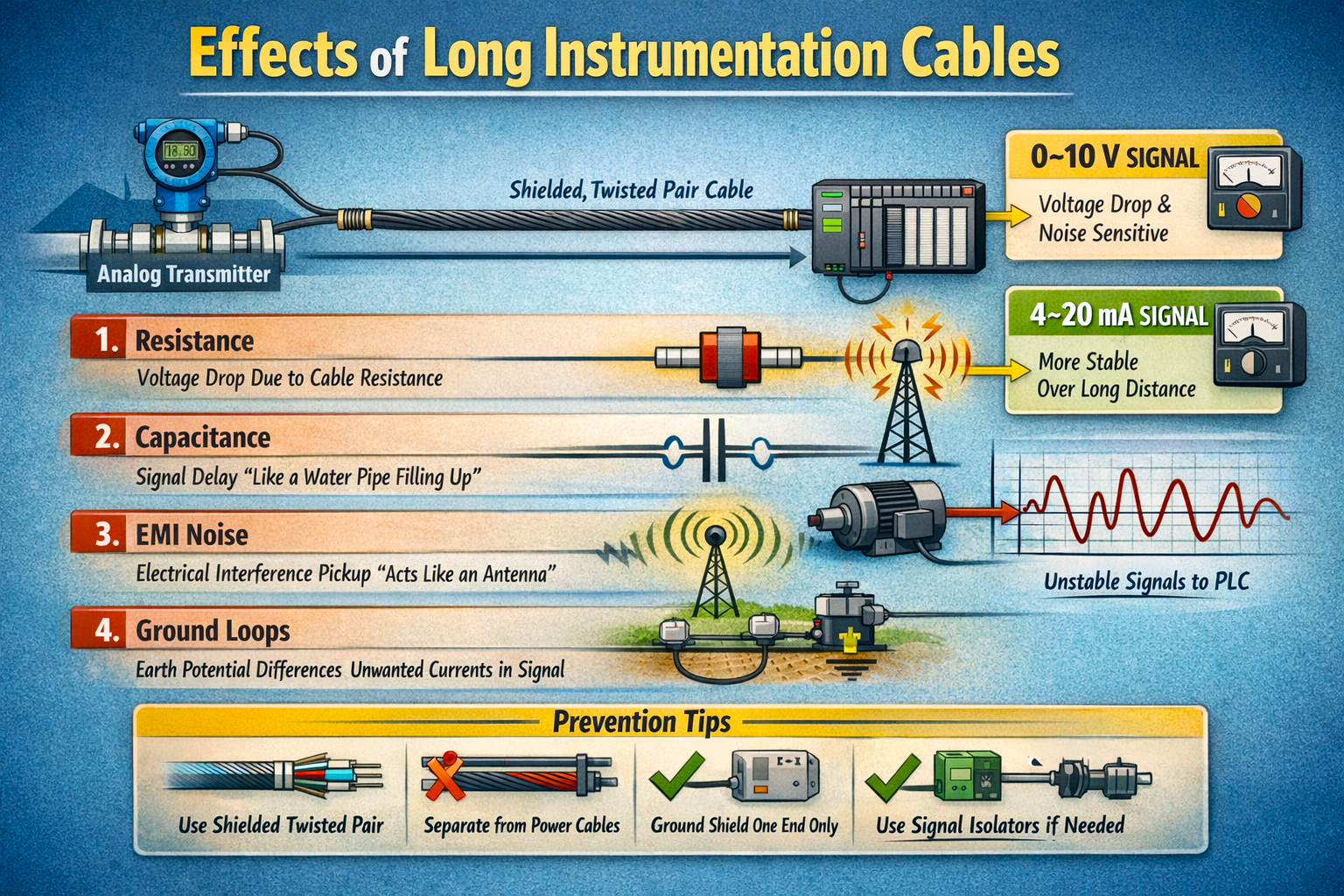
Analog input tries to measure a precise voltage or current level, which is nothing but the flow of proper electricity. Due to this, cable length directly affects the stability of the signal. In this post, we will see how cable lengths affect analog input stability.
Voltage drop in 4-20 mA or 0-10 V loop
In a 4-20 mA analog loop, the PLC analog input card does not directly read current; it measures the voltage developed across an internal precision resistor (typically 250 Ω), so the transmitter must force current through the entire loop path. That loop includes the transmitter electronics, the cable going to the PLC, the resistor inside the PLC card, and the return cable back to the power supply.
As cable length increases, the resistance of the conductors also increases, and therefore the transmitter requires more driving voltage (called compliance voltage) to maintain the full 20 mA signal. If the available loop supply voltage is not enough to overcome the combined resistance of the cable and input circuit, the transmitter cannot push the full 20 mA even though it is healthy and properly calibrated.
Instead of failing completely, the output current slightly reduces, which mainly affects the upper measurement range, so the PLC shows values lower than the actual process (for example, a full tank never indicating 100%). This creates a misleading situation where the instrument appears inaccurate while the real cause is insufficient voltage headroom due to long cable length.
A 4-20 mA loop is designed so that the current remains constant regardless of cable resistance, the PLC still receives nearly the same current, and the measurement remains stable over distance. However, as discussed earlier, the transmitter can only maintain that constant current if it has sufficient compliance voltage available. As cable length increases, the loop resistance rises, and the transmitter must generate a higher voltage to push the same current. When this voltage requirement exceeds what the power supply and transmitter can provide, the current begins to reduce, especially near 20 mA, and the PLC reads a lower value.
In a 0-10 V system, the PLC measures the exact voltage that arrives at its input terminals. Whatever voltage reaches the PLC is treated as the process value. When the cable becomes long, the resistance of the conductor causes a voltage drop along the wire itself. So even if the transmitter sends 10 V, a smaller voltage actually reaches the PLC. The PLC calculates a lower process value. In addition, any electrical noise induced into the cable directly adds to or subtracts from the measured voltage, so the reading easily fluctuates. Because the measurement depends entirely on the voltage present at the PLC terminals, cable length, loose terminals, corrosion, and nearby electrical equipment all immediately affect accuracy.
So the difference is important: in 0-10 V systems, cable length directly alters the measured signal reaching the PLC, while in 4-20 mA systems, cable length indirectly affects the signal by exhausting the transmitter’s driving capability. That is why industry strongly prefers 4-20 mA for field instruments located far from the control panel.
Cable capacitance
When an analog transmitter is connected to a PLC, the signal does not travel through a single wire. A complete electrical loop is required, so the cable always contains two conductors – one carrying the signal to the PLC and the other returning it to the power supply. These two wires run side-by-side for the entire cable length and are separated only by insulation. Because of this physical arrangement, the cable does not behave as a simple piece of copper. Electrically, it automatically forms a small capacitor, even though no capacitor was intentionally installed.
As cable length increases, this effect becomes noticeable. A capacitor has the property of temporarily storing electrical charge. Therefore, when the transmitter output changes, the signal does not instantly appear at the PLC. Part of the energy first charges the cable, and only afterward does the new signal reach the analog input card. When the signal rises, the PLC reading increases slowly instead of immediately; when the signal falls, the cable releases its stored charge and briefly continues supplying current, so the PLC value decreases gradually rather than suddenly.
This creates a measurement delay. The transmitter may already be showing the correct process value, but the PLC is seeing a slightly older value of the process. The longer the cable, the larger this delay becomes. For slow-changing measurements like tank level, it is rarely noticeable, but for fast signals such as flow or pressure, it becomes important because the control system reacts to outdated information.
Noise pickup and electromagnetic interference
In an industrial plant, the environment is electrically very noisy. Motors, VFD drives, contactors, soft starters, heaters, and large power cables continuously create changing magnetic and electric fields around them. A short cable hardly interacts with these fields, but a long analog cable behaves differently, and it starts acting like an antenna.
As the cable length increases, its exposure area also increases. The changing magnetic fields produced, especially during motor starting or VFD switching, induce small unwanted voltages in the signal wires. For a digital signal, this is usually harmless because the PLC only checks ON or OFF. However, an analog input is measuring a very small and precise electrical quantity, so even a tiny induced voltage disturbs the reading.
This effect is most severe in 0-10 V signals because the PLC directly measures the incoming voltage. A few tens of millivolts of induced noise can already create a noticeable percentage error, and the PLC value begins to jump up and down. In 4-20 mA loops, the effect is smaller because the signal is represented by current rather than voltage, but the noise can still enter the input electronics and appear as fluctuations, especially if shielding or grounding is poor.
A common field observation clearly indicates this problem – when a nearby motor starts or a VFD ramps up, the analog value suddenly spikes or dips for a moment, even though the process did not change. Flow may briefly show 120%, level may momentarily jump, or pressure may oscillate during equipment startup. The transmitter is not faulty, but the electrical interference is being induced into the long cable.
Ground loop effects
Another problem that appears mainly with long analog cables is ground loop error. In a plant, the field instrument and the PLC panel are usually located far apart, and both are connected to earth at different physical locations. These two earth points are never at exactly the same electrical potential. Because of soil resistance, load currents, lightning protection systems, and large equipment operating nearby, a small voltage difference can exist between the field earth and the panel earth.
When a long analog cable connects these two locations, that small voltage difference tries to equalize through the signal wiring or its shield. A tiny unwanted current then starts flowing in the measurement circuit, even though it is not part of the actual process signal. The PLC analog input cannot distinguish between real signal current and this extra current, so it interprets it as a change in process value.
Unlike electrical noise, this problem does not create sudden spikes. Instead, it produces a slow drifting or constantly unstable reading. The process may be perfectly steady, but the PLC value keeps wandering up and down slightly. You may also notice that the reading changes between day and night or when large equipment in another part of the plant starts operating, because the earth’s potential difference is changing. This issue is especially seen when cable shields are grounded at both ends. The shield then becomes a conductor between two earth points and carries a circulating current, which couples into the signal pair. The longer the cable, the higher the possibility and magnitude of this effect.
In this way, we saw how cable lengths affect analog input stability.