Inst ToolsInst ToolsInst Tools
  • Courses
  • Automation
    • PLC
    • Control System
    • Safety System
    • Communication
    • Fire & Gas System
  • Instrumentation
    • Design
    • Pressure
    • Temperature
    • Flow
    • Level
    • Vibration
    • Analyzer
    • Control Valve
    • Switch
    • Calibration
    • Erection & Commissioning
  • Interview
    • Instrumentation
    • Electrical
    • Electronics
    • Practical
  • Q&A
    • Instrumentation
    • Control System
    • Electrical
    • Electronics
    • Analog Electronics
    • Digital Electronics
    • Power Electronics
    • Microprocessor
  • Request
Search
  • Books
  • Software
  • Projects
  • Process
  • Tools
  • Basics
  • Formula
  • Power Plant
  • Root Cause Analysis
  • Electrical Basics
  • Animation
  • Standards
  • 4-20 mA Course
  • Siemens PLC Course
Reading: How a 4 Wire RTD Works ?
Share
Font ResizerAa
Inst ToolsInst Tools
Font ResizerAa
  • Courses
  • Design
  • PLC
  • Interview
  • Control System
Search
  • Courses
  • Automation
    • PLC
    • Control System
    • Safety System
    • Communication
    • Fire & Gas System
  • Instrumentation
    • Design
    • Pressure
    • Temperature
    • Flow
    • Level
    • Vibration
    • Analyzer
    • Control Valve
    • Switch
    • Calibration
    • Erection & Commissioning
  • Interview
    • Instrumentation
    • Electrical
    • Electronics
    • Practical
  • Q&A
    • Instrumentation
    • Control System
    • Electrical
    • Electronics
    • Analog Electronics
    • Digital Electronics
    • Power Electronics
    • Microprocessor
  • Request
Follow US
All rights reserved. Reproduction in whole or in part without written permission is prohibited.
Inst Tools > Blog > Temperature Measurement > How a 4 Wire RTD Works ?

How a 4 Wire RTD Works ?

Last updated: March 16, 2018 5:56 am
Editorial Staff
Temperature Measurement
No Comments
Share
2 Min Read
SHARE

4 Wire RTD Principle

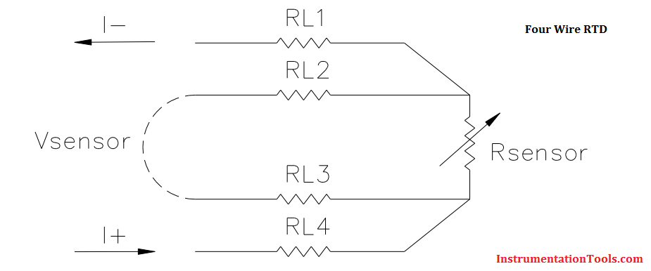
The most accurate lead wire configuration is the “true” 4-wire configuration. In a true 4- wire configuration, the resistance of the lead wires does not contribute to the resistance of the sensor.

4-wire construction is used primarily where close accuracy is required. In a 4 wire RTD the actual resistance of the lead wires can be determined and removed from the sensor measurement.

The true 4-wire measurement uses the current-potential method. A current of known value (I+) is passed through the sensor along the “current” lead wires. The voltage generated across the sensor is measured using the “potential” lead wires (Vsensor) and the sensor’s resistance is calculated by dividing the measured voltage by the Known current.

Four Wire RTD Principle

4 Wire RTD Formula

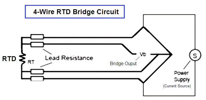
The 4-wire circuit is a true 4-wire bridge, which works by using wires 1 & 4 to power the circuit and wires 2 & 3 to read. This true bridge method will compensate for any differences in lead wire resistances.

The resistance of the lead wires is not a factor because:

  • The value of the current is equal at any point in the circuit. It is independent of the resistance of the lead wire.
  • The input impedance of the voltage measurement circuitry is high enough to prevent any significant current flow in the voltage leads. Since no current is flowing, the voltage along the potential leads does not change along their length.

4-wire RTD Bridge Circuit

4-wire RTD Bridge Circuit

Also Read: 2 Wire Vs 3 Wire Vs 4 Wire RTD’s
Don't Miss Our Updates
Be the first to get exclusive content straight to your email.
We promise not to spam you. You can unsubscribe at any time.
Invalid email address
You've successfully subscribed !

Continue Reading

Testing thermocouples and RTDs using Multi-function Calibrators
Basics of Thermocouples and RTD
Thermocouple Temperature Range Questions and Answers
Introduction to RTDs
What is a Four-wire RTD ?
Different Types of Thermometers
Share This Article
Facebook Whatsapp Whatsapp LinkedIn Copy Link
Share
Leave a Comment

Leave a Reply Cancel reply

Your email address will not be published. Required fields are marked *

Stay Connected

128.3kFollowersLike
69.1kFollowersFollow
210kSubscribersSubscribe
38kFollowersFollow

Categories

Explore More

What to Choose RTD or Thermocouple ?
Applications of Temperature Scanner
Resistance Temperature Detectors Troubleshooting Tips
Temperature Sensor calibration procedure
General Specification of Thermowell
Thermowell Wake Frequency Calculation
Spiral Bimetallic Thermometer Principle
What is Temperature ?

Keep Learning

Stability and Uniformity of Temperature Bath

Stability and Uniformity of Temperature Bath

thermal imaging instrument

Thermal Imaging Temperature Measurement

RTD with Thermowell

Temperature Sensor Accessories

non-contact pyrometers distance calculation

Non-contact Pyrometers Characteristics

non-contact pyrometer principle

Non-contact Temperature Sensors

Liquid In Glass Thermometers

Liquid In Glass Thermometer Principle

Thermocouple Reference Junction

Thermocouple Working Principle

RTD Testing Methods

RTD Testing Methods in Calibration Laboratory

Learn More

calibrating low-pressure instrument

Simulate Different Values for Pressure Instrument Under Test

Reed Switch Principle

Reed switch Working Principle

Seebeck Effect

Seebeck Effect Theory

Open Platform Communication (OPC)

Open Platform Communication (OPC)

NDIR gas analysis

Non-Dispersive Analyzers

Manometer with two different liquids

Calculate the Height of Glycerine

Proportional only Control Theory

Proportional-only Control Theory

operational-amplifiers-questions-answers

Operational Amplifiers Questions & Answers

Menu

  • About
  • Privacy Policy
  • Copyright

Quick Links

  • Learn PLC
  • Helping Hand
  • Part Time Job

YouTube Subscribe

Follow US
All rights reserved. Reproduction in whole or in part without written permission is prohibited.
Welcome Back!

Sign in to your account

Username or Email Address
Password

Lost your password?