Hot Wire Anemometer works When an electrically heated wire is placed in a flowing gas stream, heat is transferred from the wire to the gas and hence the temperature of the wire reduces, and due to this, the resistance of the wire also changes. This change in resistance of the wire becomes a measure of flow rate.
Hot Wire Anemometer Principle

The main parts of the arrangement are as follows:
- Conducting wires placed in a ceramic body.
- Leads are taken from the conducting wires and they are connected to one of the limbs of the wheat stone bridge to enable the measurement of change in resistance of the wire.
Types of Hot wire Anemometer
There are two methods of measuring flow rate using an anemometer bridge combination namely:
- Constant current method
- Constant temperature method
Constant current method Hot wire Anemometer

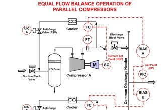
The bridge arrangement along with the anemometer has been shown in diagram. The anemometer is kept in the flowing gas stream to measure flow rate.
A constant current is passed through the sensing wire. That is, the voltage across the bridge circuit is kept constant, that is, not varied.
Due to the gas flow, heat transfer takes place from the sensing wire to the flowing gas and hence the temperature of the sensing wire reduces causing a change in the resistance of the sensing wire. (this change in resistance becomes a measure of flow rate).
Due to this, the galvanometer which was initially at zero position deflects and this deflection of the galvanometer becomes a measure of flow rate of the gas when calibrated.
Constant temperature method Hot wire Anemometer

The bridge arrangement along with the anemometer has been shown in diagram. The anemometer is kept in the flowing gas stream to measure flow rate.
A current is initially passed through the wire.
Due to the gas flow, heat transfer takes place from the sensing wire to the flowing gas and this tends to change the temperature and hence the resistance of the wire.
The principle in this method is to maintain the temperature and resistance of the sensing wire at a constant level. Therefore, the current through the sensing wire is increased to bring the sensing wire to have its initial resistance and temperature.
The electrical current required in bringing back the resistance and hence the temperature of the wire to its initial condition becomes a measure of flow rate of the gas when calibrated.
If you liked this article, then please subscribe to our YouTube Channel for Instrumentation, Electrical, PLC, and SCADA video tutorials.
You can also follow us on Facebook and Twitter to receive daily updates.
Read Next:
- Orifice Flow Meters Compensation
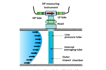
- Annubar Flow Meter Theory
- Magnetic flow meter Operation
- Nutating Disc Flow Meters
- What is a Thermal flow meter?