In this article, we will learn how the Hot-well level in Condensing Turbine is controlled.
All the Processes and the power plant operations require continuous monitoring and controlling of the process parameters to avoid the problems that occur during the operation.
But by Manual control, continuous Monitoring and Controlling of the Process parameters are not possible. Now Industrial Automation technology uses the DCS and SCADA systems to monitor and control these mechanisms that are used in the Process Industry to keep the continuous tracking of the Process Parameters and Equipment.
The DCS is state-driven. And SCADA is event-driven.
DCS Software and Hardware Details
- Make: ABB
- Controller: AC 900F
- Software Used: ABB FREELANCE 2016 SP1
- SCADA /HMI Software: Digivis
So let us see some basic terms used.
Hot Well
It is a Tank or Reservoir in which the Low-Pressure Steam or condensate water is collected and is used again as feedwater to the Boiler.
A Hot-well is also known as a Condenser in the condensing Turbine,
It is one of the most essential auxiliaries in the Power plant.

Condensing Turbine
Condensing turbine is a Turbine in which the LP Turbine is connected to a condenser. To condensate the low-Pressure Steam.
The condensing turbine results in maximum power generation and Increases the plant efficiency. The power output of a condensing turbine is sensitive to ambient conditions.
Recirculation and Main Control Valve
These Recirculation and Main Control valves are used to maintain the desired Water level in the Hot-well with a minimum water flow.
Condensate Extraction Pump
The Condensate Extraction Pump in the power plant transfers the condensate water from the Hot-well tank to the Deaerator through Ejector and GVC which is the feedback to the feed water.
The Condensate Extraction Pump (CEP) is installed below the Hot-well
Deaerator
The Deaerator in the power plant is an Auxiliary unit, which removes excess oxygen and non-condensable gases from the boiler feedwater. The Deaerator also plays important role in achieving the plant efficiency
The primary functions of the Hot-well are to
- Increase the power by maximizing the pressure drop across the condensing turbine.
- Protect the Low-Pressure Turbine blades from damage.
- Maintain the condensate level to normal condition by operating the makeup, drain, and emergency pumps based on the level of water.
The efficiency of Condensing Turbine is directly proportional to the vacuum created by condensing steam.
In the boiler, the chemical energy is converted into thermal energy by heating water and converting it into steam by burning the fuel (Bagasse) in the Furnace. The steam produced in the boiler gets expanded in the steam turbine.
In the turbine, the thermal energy of the steam is converted into Kinetic Energy which makes the turbine blades rotate.
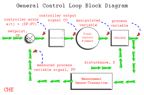
The Hot-well level control system uses a P-I controller to maintain the Hot-well level by operating the Recirculation and Main Control valves.
- The Hot well level is measured by the level transmitter,
- The 3 Level transmitters are Installed LT-501, LT-502, and LT- 503.
- The 2oo3 Logic is used to control the level.
- The current signal from the level transmitter in the range of 4-20mA DC
The level transmitter sends the Measured Value (PV) to the P-I controller, and the P-I controller compares the Measured Value with the SetPoint. The P-I controller sends the proportional signal to the Control Valves (Recirculation and Main Control valve) to maintain the Hot-well level.
The Interlocks are provided For CEP:
- Hot well Level SetPoint for CEP Start is 70 %
- Hot well Level SetPoint for CEP Stop is 60 %
Maintaining the Hot-well Level through DCS
The DCS output is Fed to the I-P Converter from which Controlled Air or Instrument Air is fed to both the Valves in the Split Range Mode of Control, If the Hot-well level is lesser or Greater than the SetPoint, the respective Error signal is generated from the P-I Controller and is fed to the Valves through I-P Converter.
The 2 Valves are provided for maintaining the Hot-well level they are:
Recirculation Valve called “Air to Open”
This valve operates at a range of 2.0 kg/cm2 to 2.8 kg/cm2 this valve remains fully closed from 0.2 kg/cm2 to 2.0 kg/cm2 of air Pressure. And starts opening as air pressure goes beyond 2.0 kg/cm2.
It gets fully opened as the air pressure increases from 2.0 kg/cm2 to 2.8 kg/cm2.
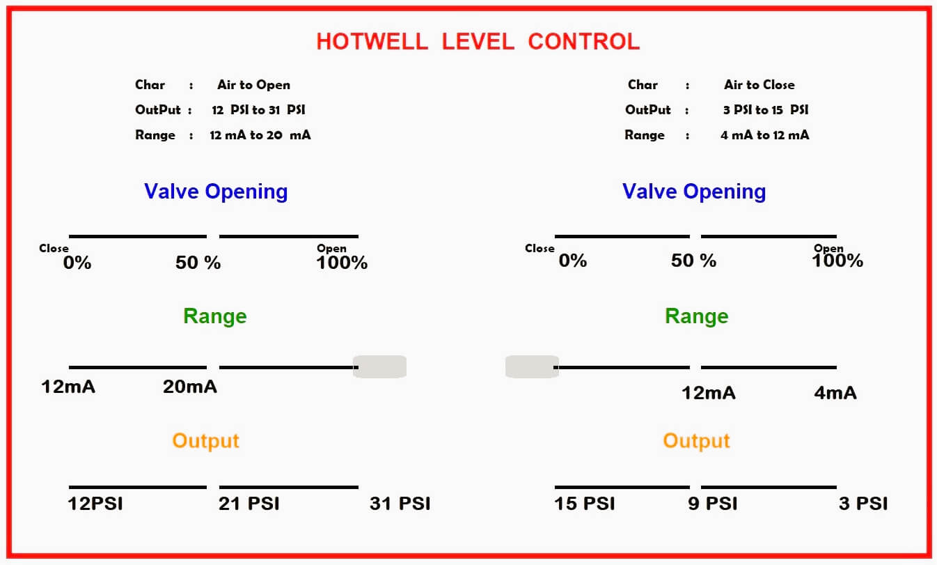
If the Hot-well level reduces below the SetPoint SP > PV, then the P-I Controller sends the proportional signal to the Recirculation Valve to get open, and the water from the Deaerator will flow back into the Hot-well to maintain the level.
Main Control Valve called “Air to Close”
This valve operates at a range of 0.2 kg/cm2 to 1.0 kg/cm2 of air Pressure, this valve remains fully open and starts closing as air pressure starts building up from 0.2 kg/cm2 onwards, this valve gets fully closed at 1.0 kg/cm2 of air pressure.
If the Hot Well level rises above the SetPoint SP < PV, then the P-I Controller sends the Proportional signal to the Main Control Valve to get open and the excess water from the Hot-well will flow to the Deaerator to maintain the desired Hot Well level to normal.
Hotwell Operation
The Main Steam after passing through the various stages of the Turbine goes to the condenser through the Low-Pressure side of the turbine. The Density, Temperature, and Pressure of the Steam are reduced and are turned into condensate.
A vacuum pressure of 60 kg/cm2 – 70 kg/cm2 is applied at the condenser to suck the Low-Pressure steam into the Hot-well. Finally, the condensed steam reaches the calandria of the Hot-well tank.
Now the cooling water is taken from the cooling tower and is passed through the Horizontal tubes to condense the steam into the water, and the water is collected at the condenser Tank.
Here, the temperature of the water in the condenser Tank will be 30 to 40 degrees Celsius approximately equivalent to the Ambient Temperature.
Note: The mentioned pressure/temperature values may change depending on the model and plant installation.
What happens if the Hot-well level varies?
The undesired Hot-well level affects power plant efficiency hence the water level should be maintained to a Normal point.
For a safe operation of the Power plant, the Hot-well level is to be maintained to 60% of its Range.
- If the Hot-well level goes below 60%, the vacuum level gets increased so that the LP turbine blades get sucked along with the steam by the vacuum pressure and the CEP loses its suction pressure and begins Cavitating
- If the Hot well level rises above 60%, then deterioration of the vacuum takes place. And the water travels to Low – Pressure Turbine Blades causing damage to the rotor Blades.
Advantages of Maintaining the Hot-well level
- To provide the Net Positive Suction Head (NPSH) to the condensate pump. CEP loses its suction pressure and begins Cavitating when the level in the Hot well reduces.
- To absorb the water droplets from the Low-Pressure steam.


Wow….thanks for this knowledge,I can confess I have added knowledge to myself..Am an instrument technician Working in a power generation plant