Inst ToolsInst ToolsInst Tools
  • Courses
  • Automation
    • PLC
    • Control System
    • Safety System
    • Communication
    • Fire & Gas System
  • Instrumentation
    • Design
    • Pressure
    • Temperature
    • Flow
    • Level
    • Vibration
    • Analyzer
    • Control Valve
    • Switch
    • Calibration
    • Erection & Commissioning
  • Interview
    • Instrumentation
    • Electrical
    • Electronics
    • Practical
  • Q&A
    • Instrumentation
    • Control System
    • Electrical
    • Electronics
    • Analog Electronics
    • Digital Electronics
    • Power Electronics
    • Microprocessor
  • Request
Search
  • Books
  • Software
  • Projects
  • Process
  • Tools
  • Basics
  • Formula
  • Power Plant
  • Root Cause Analysis
  • Electrical Basics
  • Animation
  • Standards
  • 4-20 mA Course
  • Siemens PLC Course
Reading: Half Wave Rectifier Principle
Share
Font ResizerAa
Inst ToolsInst Tools
Font ResizerAa
  • Courses
  • Design
  • PLC
  • Interview
  • Control System
Search
  • Courses
  • Automation
    • PLC
    • Control System
    • Safety System
    • Communication
    • Fire & Gas System
  • Instrumentation
    • Design
    • Pressure
    • Temperature
    • Flow
    • Level
    • Vibration
    • Analyzer
    • Control Valve
    • Switch
    • Calibration
    • Erection & Commissioning
  • Interview
    • Instrumentation
    • Electrical
    • Electronics
    • Practical
  • Q&A
    • Instrumentation
    • Control System
    • Electrical
    • Electronics
    • Analog Electronics
    • Digital Electronics
    • Power Electronics
    • Microprocessor
  • Request
Follow US
All rights reserved. Reproduction in whole or in part without written permission is prohibited.
Inst Tools > Blog > Electronic Devices & Circuits > Half Wave Rectifier Principle

Half Wave Rectifier Principle

Last updated: September 30, 2016 11:20 am
Editorial Staff
Electronic Devices & Circuits Electronics Animation
No Comments
Share
3 Min Read
SHARE

Half Wave Rectifier :

half-wave-rectifier-principle

Half-Wave Rectifier Operation

Half Wave Rectifier Working Animation

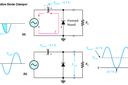
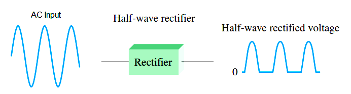
The below Figure illustrates the process called half-wave rectification. A diode is connected to an ac source and to a load resistor, RL, forming a half-wave rectifier. Keep in mind that all ground symbols represent the same point electrically. Let’s examine what happens during one cycle of the input voltage using the ideal model for the diode. When the sinusoidal input voltage (Vin) goes positive, the diode is forward-biased and conducts current through the load resistor, as shown in part (a). The current produces an output voltage across the load RL, which has the same shape as the positive half-cycle of the input voltage.

half-wave-rectifier-operation

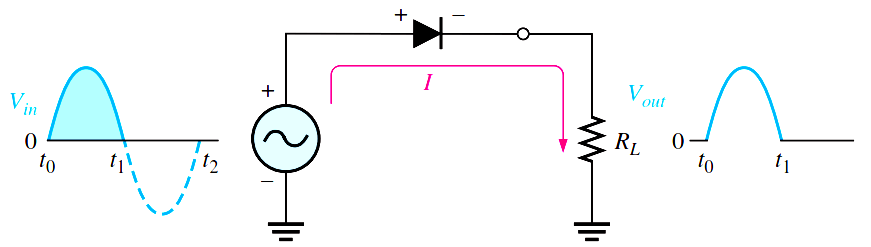
(a) During the positive alternation of the AC input voltage, the output voltage looks like the positive half of the input voltage. The current path is through ground back to the source.

half-wave-rectifier-working


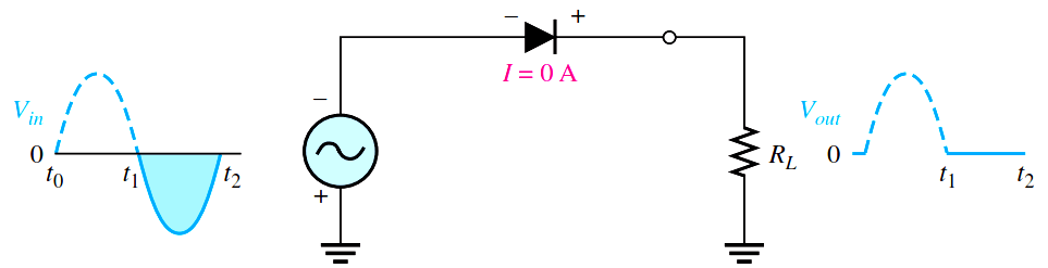
(b) During the negative alternation of the input voltage, the current is 0, so the output voltage is also 0.

half-wave-rectifier-output-cycles

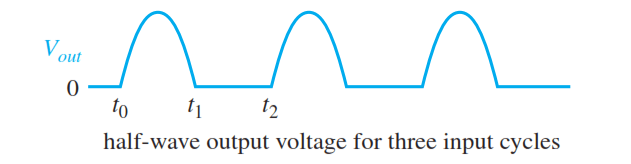
When the input voltage goes negative during the second half of its cycle, the diode is reverse-biased. There is no current, so the voltage across the load resistor is 0 V, as shown in Figure (b). The net result is that only the positive half-cycles of the ac input voltage appear across the load. Since the output does not change polarity, it is a pulsating dc voltage output as shown in above figure.

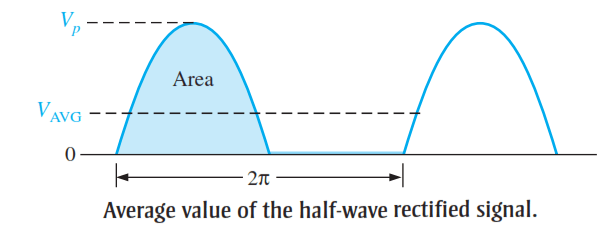
Average Value of the Half-Wave Output Voltage

The average value of the half-wave rectified output voltage is the value you would measure on a dc voltmeter. Mathematically, it is determined by finding the area under the curve over a full cycle, as illustrated in Below Figure, and then dividing by 2p, the number of radians in a full cycle. The result of this is expressed in below Equation , where Vp is the peak value of the voltage. This equation shows that VAVG is

average-value-of-the-half-wave-output-voltage

average-value-of-the-half-wave-rectifier-output-voltage

Effect of the Barrier Potential on the Half-Wave Rectifier Output

When the practical diode model is used with the barrier potential of 0.7 V taken into account, this is what happens. During the positive half-cycle, the input voltage must overcome the barrier potential before the diode becomes forward-biased. This results in a half-wave output with a peak value that is 0.7 V less than the peak value of the input. The expression for the peak output voltage is

Effect-of-the-barrier-potential-on-the-half-wave-rectifier-output

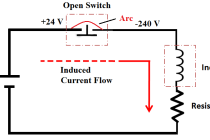
Peak Inverse Voltage (PIV)

The peak inverse voltage (PIV) equals the peak value of the input voltage, and the diode must be capable of withstanding this amount of repetitive reverse voltage. For the diode, the maximum value of reverse voltage, designated as PIV, occurs at the peak of each negative alternation of the input voltage when the diode is reverse-biased. A diode should be rated at least 20% higher than the PIV.

half-wave-rectifier-peak-inverse-voltage

Don't Miss Our Updates
Be the first to get exclusive content straight to your email.
We promise not to spam you. You can unsubscribe at any time.
Invalid email address
You've successfully subscribed !

Continue Reading

JFET Working Animation
Laser Diode Working Principle
Current Divider Rule
Short Circuit and Open Circuit
Band Gap for Semiconductor Materials
Combining Independent Current Sources in Parallel
Share This Article
Facebook Whatsapp Whatsapp LinkedIn Copy Link
Share
Leave a Comment

Leave a Reply Cancel reply

Your email address will not be published. Required fields are marked *

Stay Connected

128.3kFollowersLike
69.1kFollowersFollow
210kSubscribersSubscribe
38kFollowersFollow

Categories

Explore More

Zener Diode Limiter
Semiconductors Diodes Questions & Answers
Phototransistor Circuit Example
Cathode Ray Tube (CRT)
Full Wave Rectifier
What is Kirchhoff’s Current Law
Transistor Stabilisation
Transistor as Amplifier

Keep Learning

Field Instruments Questions and Answers

Basics of Amplifiers Interview Questions

Photodiode as Variable Resistance Device

Photodiode as Variable Resistance Device

Types-of-diodes

Different Types of Diodes

Schottky Diode Vs PN junction Diode

Difference between Schottky Diode and PN junction Diode

What is a Memristor

What is a Memristor? Principle, Advantages, Applications

Why Silicon is preferred over Germanium ?

Why Silicon is preferred over Germanium ?

seven-segment-display-circuit

Seven Segment Display Working Principle

Comparison of MOSFET and BJT

Comparison of MOSFET and BJT

Learn More

Power Electronics Objective Questions

PWM Inverter Quiz

Different PLC available in the Simatic S7 generation

Overview of SIEMENS PLC – S7-1500, S7-1200, S7-400, S7-300

solenoid valves trip

Identify Solenoid Valves Energized or de-energized?

Sensors Objective Questions

Sensors Objective Questions

PCB Making Machine

Beyond FR-4: Exploring Novel Materials for PCB Fabrication

Power Systems Questions & Answers

Power Systems MCQ Series 4

Helix Bimetallic Thermometer Principle

Helix Bimetallic Thermometer Principle

how-a-plc-do-the-scaling-for-a-sensor

How a PLC do the Scaling for a Sensor ?

Menu

  • About
  • Privacy Policy
  • Copyright

Quick Links

  • Learn PLC
  • Helping Hand
  • Part Time Job

YouTube Subscribe

Follow US
All rights reserved. Reproduction in whole or in part without written permission is prohibited.
Welcome Back!

Sign in to your account

Username or Email Address
Password

Lost your password?