Inst ToolsInst ToolsInst Tools
  • Courses
  • Automation
    • PLC
    • Control System
    • Safety System
    • Communication
    • Fire & Gas System
  • Instrumentation
    • Design
    • Pressure
    • Temperature
    • Flow
    • Level
    • Vibration
    • Analyzer
    • Control Valve
    • Switch
    • Calibration
    • Erection & Commissioning
  • Interview
    • Instrumentation
    • Electrical
    • Electronics
    • Practical
  • Q&A
    • Instrumentation
    • Control System
    • Electrical
    • Electronics
    • Analog Electronics
    • Digital Electronics
    • Power Electronics
    • Microprocessor
  • Request
Search
  • Books
  • Software
  • Projects
  • Process
  • Tools
  • Basics
  • Formula
  • Power Plant
  • Root Cause Analysis
  • Electrical Basics
  • Animation
  • Standards
  • 4-20 mA Course
  • Siemens PLC Course
Reading: Half-Wave Rectifier Circuit
Share
Font ResizerAa
Inst ToolsInst Tools
Font ResizerAa
  • Courses
  • Design
  • PLC
  • Interview
  • Control System
Search
  • Courses
  • Automation
    • PLC
    • Control System
    • Safety System
    • Communication
    • Fire & Gas System
  • Instrumentation
    • Design
    • Pressure
    • Temperature
    • Flow
    • Level
    • Vibration
    • Analyzer
    • Control Valve
    • Switch
    • Calibration
    • Erection & Commissioning
  • Interview
    • Instrumentation
    • Electrical
    • Electronics
    • Practical
  • Q&A
    • Instrumentation
    • Control System
    • Electrical
    • Electronics
    • Analog Electronics
    • Digital Electronics
    • Power Electronics
    • Microprocessor
  • Request
Follow US
All rights reserved. Reproduction in whole or in part without written permission is prohibited.
Inst Tools > Blog > Electrical Theory > Half-Wave Rectifier Circuit

Half-Wave Rectifier Circuit

Last updated: July 22, 2018 10:28 pm
Editorial Staff
Electrical Theory
No Comments
Share
1 Min Read
SHARE

When a diode is connected to a source of alternating voltage, it will be alternately forward-biased, and then reverse-biased, during each cycle of the AC sine-wave. When a single diode is used in a rectifier circuit, current will flow through the circuit only during one-half of the input voltage cycle (Figure 6). For this reason, this rectifier circuit is called a half-wave rectifier. The output of a half-wave rectifier circuit is pulsating DC.

Half-Wave Rectifier Circuit

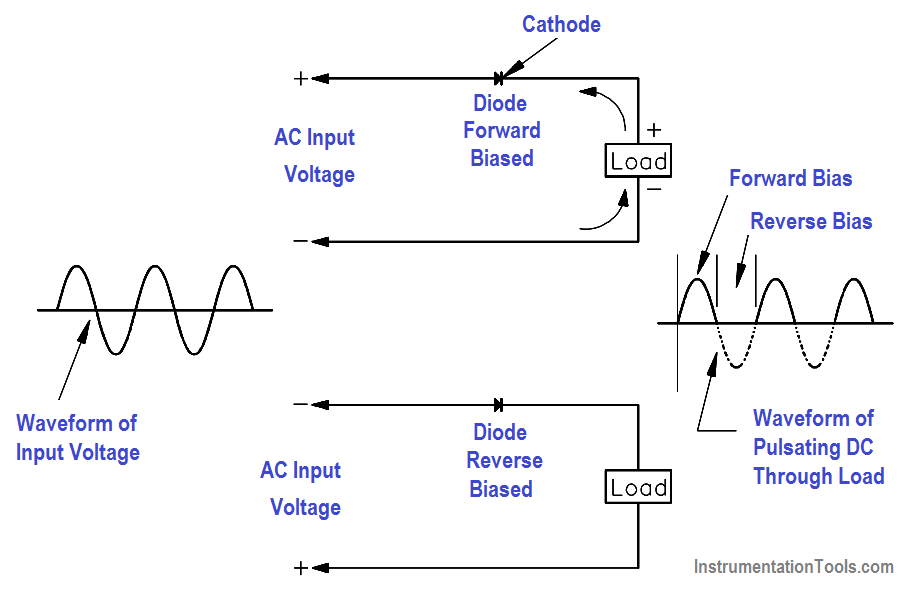
Figure 6 Half-Wave Rectifier

Don't Miss Our Updates
Be the first to get exclusive content straight to your email.
We promise not to spam you. You can unsubscribe at any time.
Invalid email address
You've successfully subscribed !

Continue Reading

Voltage Polarity and Current Direction
Losses in AC Generator
Capacitance
Calculate Power in Parallel RL Circuit
AC Generator Theory
Generator Action in a Motor
Share This Article
Facebook Whatsapp Whatsapp LinkedIn Copy Link
Share
Leave a Comment

Leave a Reply Cancel reply

Your email address will not be published. Required fields are marked *

Stay Connected

128.3kFollowersLike
69.1kFollowersFollow
210kSubscribersSubscribe
38kFollowersFollow

Categories

Explore More

Three Phase Transformer Connections
Voltage and Current Phase Relationships in an Inductive Circuit
Transformer Current Ratio
Battery Terminology
Transformer Mutual Induction
Battery Hazards
Transformer Turns Ratio
Starting a Synchronous Motor

Keep Learning

Moving Iron Vane Meter Movement

Moving Iron Vane Meter Movement

Simple RC Circuit

Impedance in RC Circuits

Electric Short Circuit

Electric Circuit : Open & Short Circuits

Series-Wound DC Generator Principle

Series-Wound DC Generators

DC Generator

DC Generator

Electrodynamometer Movement Principle

Electro-Dynamo Meter Movement

Generator Action in a Motor

What is Synchroscope ?

Transformer Efficiency

Transformer Efficiency

Learn More

Difference Between AIS and GIS Panels

Difference Between AIS and GIS Panels

two chemical streams are mixed together

Practical Process Control System Questions & Answers – 8

Feedforward control with feedback trim

Feedforward Control Principle

Structured Text Selector Machine Logic

Write a PLC Program for Selector Machine using Structured Text

wedge Flow meter

What is a Segmental Wedge Flow Meter?

AC Generator Nameplate Ratings

AC Generator Nameplate Ratings

Gas Holder Level Measurement

Measurements in Air and Fuel Circuit in Power Plant

Basic Power Electronics Interview Questions

Basic Power Electronics Interview Questions

Menu

  • About
  • Privacy Policy
  • Copyright

Quick Links

  • Learn PLC
  • Helping Hand
  • Part Time Job

YouTube Subscribe

Follow US
All rights reserved. Reproduction in whole or in part without written permission is prohibited.
Welcome Back!

Sign in to your account

Username or Email Address
Password

Lost your password?