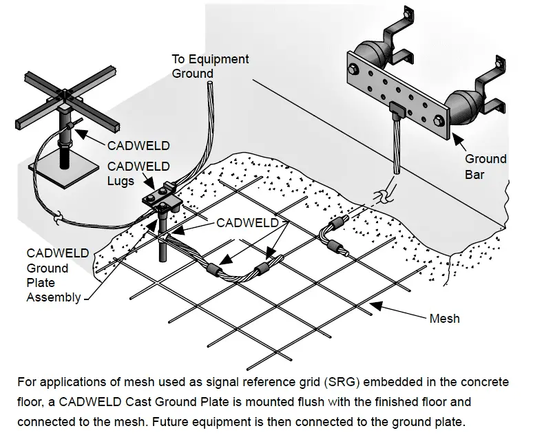
When a metallic mesh is embedded in the structural concrete subfloor, it may be used for an electronic signal reference grid (SRG). When this is done the problem becomes how to make connections to the SRG. The typical approach is to embed a ground plate at each intersection of the SRG’s conductors, but on a spacing of around 2×2 or 4×4 feet square. This conforms to the standard practices for SRGs such as those used in conjunction with a computer room’s cellular raised floor.
In other cases where connection points on 2-foot centers are not needed, a ground connection plate per Figure may be installed wherever necessary. The exposed surface of the embedded stud or tie-plate is then used to make connections to and from the SRG that is below the surface of the concrete.

Note that for electrical equipment and mechanical equipment rooms, spacings of 2×2 feet are often closer than is needed— especially if the floorplan is known in advance. In these cases the concrete embedded SRG studs or ground plates are installed to place them close to the equipment that is planned to be permanently installed in the room. Spacings of around 4 to 6 feet square are common in these kinds of cases.
The concrete floor embedded SRG is often combined with the steel reinforcing bar system that is installed in the poured concrete. In some cases where the reinforcing steel system is welded together, it can serve as the actual SRG, otherwise the reinforcing steel is simply periodically welded to the SRG at those points where the two structures have nearby or intersecting elements.
Workstations that are part of a network and use Local Area Network (LAN) interface plug-in cards or modems, or are connected to servers, printers, or similar peripheral devices that are not located at the workstation, typically need special attention to be paid to how they are grounded so that common-mode noise will not be a significant problem with their operation.
Accordingly, here are some suggestions:
Provide an externally applied supplementary equipment grounding conductor network that is connected to each item of the workstation and to the “greenwire” of the branch circuit(s) serving the workstation.
If there is any excess length in the ac power line cords or data signal cables used to connect the workstation’s equipment to the branch circuit or network’s signal circuits, loop the excess into a small coil whose loops are secured by tie-wraps or plastic electrical tape.
This creates a “choke” effect that can reduce the higher frequency common-mode noise currents in the path to which the technique is applied, and without affecting the power or signal transport process. Observe bending radius limits of conductors to avoid overstressing the insulation or causing excessive heat rise.
Electromagnetic Interference (EMI) in the form of coupled radio waves into signal cables, is not a common problem in most installations.
However, it is not an unknown problem either, especially if the source of the EMI is located close to the affected cable and its served circuits. Where interference with low-level signal processes is encountered and if traced to EMI at radio frequencies such as from a radio transmitter or some other industrial process occurring at radio frequencies, additional signal cable shielding and in extreme cases signal filtering at the cable’s ends, may need to be provided on the affected circuits.
The application of such filters may need to be carried out inside of the related equipment, so close involvement of the equipment’s original manufacturer (OEM) is very important.
Grounding of telecommunications systems, such as voice and data grade telephone circuits, has become a well defined area of grounding.
The rules are explicit. If not followed, the systems will be more sensitive to noise disturbances.
As with other forms of electronic systems grounding, there is no conflict between a safe system and a reliable one. In all cases, the NEC’s requirements fully apply to all aspects of the telecommunications wiring.
The proper installation of telecommunications circuits is generally beyond the scope of this document, but some helpful references are provided as follows:
(1) ANSI/EIA/TIA Standard 569A-1997 Commercial Building Telecommunications Cabling Standard
(2) ANSI/EIA/TIA Standard 569-1990, Commercial Building Standard for Telecommunications Pathways and Spaces
(3) ANSI/EIA/TIA Standard 570-1991, Residential and Light Commercial Telecommunications Wiring Standard
Do you face any problems with grounding? Share with us.
Reference: erico
In this post, we will learn the basic requirements for a network switch to be…
The PLC panel and MCC panel interface signals are start, stop, run feedback, trip, local…
In this article, we are going to discuss about shutter door control using induction motor…
Electrical Drives control the motion of electric motors. Motion control is required in industrial and…
PLC ladder logic design to control 3 motors with toggle switch and explain the program…
VFD simulator download: Master the online tool from the Yaskawa V1000 & programming software for…
View Comments
Dear Team
Very good information sharing regarding the Grounding on various system
Thanks for the same.