Inst ToolsInst ToolsInst Tools
  • Courses
  • Automation
    • PLC
    • Control System
    • Safety System
    • Communication
    • Fire & Gas System
  • Instrumentation
    • Design
    • Pressure
    • Temperature
    • Flow
    • Level
    • Vibration
    • Analyzer
    • Control Valve
    • Switch
    • Calibration
    • Erection & Commissioning
  • Interview
    • Instrumentation
    • Electrical
    • Electronics
    • Practical
  • Q&A
    • Instrumentation
    • Control System
    • Electrical
    • Electronics
    • Analog Electronics
    • Digital Electronics
    • Power Electronics
    • Microprocessor
  • Request
Search
  • Books
  • Software
  • Projects
  • Process
  • Tools
  • Basics
  • Formula
  • Power Plant
  • Root Cause Analysis
  • Electrical Basics
  • Animation
  • Standards
  • 4-20 mA Course
  • Siemens PLC Course
Reading: Generator Action in a Motor
Share
Font ResizerAa
Inst ToolsInst Tools
Font ResizerAa
  • Courses
  • Design
  • PLC
  • Interview
  • Control System
Search
  • Courses
  • Automation
    • PLC
    • Control System
    • Safety System
    • Communication
    • Fire & Gas System
  • Instrumentation
    • Design
    • Pressure
    • Temperature
    • Flow
    • Level
    • Vibration
    • Analyzer
    • Control Valve
    • Switch
    • Calibration
    • Erection & Commissioning
  • Interview
    • Instrumentation
    • Electrical
    • Electronics
    • Practical
  • Q&A
    • Instrumentation
    • Control System
    • Electrical
    • Electronics
    • Analog Electronics
    • Digital Electronics
    • Power Electronics
    • Microprocessor
  • Request
Follow US
All rights reserved. Reproduction in whole or in part without written permission is prohibited.
Inst Tools > Blog > Electrical Theory > Generator Action in a Motor

Generator Action in a Motor

Last updated: July 29, 2018 11:14 am
Editorial Staff
Electrical Theory
No Comments
Share
2 Min Read
SHARE

A generator action is developed in every motor. When a conductor cuts lines of force, an EMF is induced in that conductor.

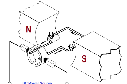
Current to start the armature turning will flow in the direction determined by the applied DC power source. After rotation starts, the conductor cuts lines of force. By applying the left-hand rule for generators, the EMF that is induced in the armature will produce a current in the opposite direction. The induced EMF, as a result of motor operation, is called counter-electromotive force, or CEMF, as illustrated in Figure 6.
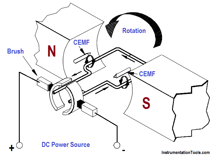
Generator Action in a Motor

Since the CEMF is generated by the action of the armature cutting lines of force, the value of CEMF will depend on field strength and armature speed, as shown in Equation.

ECEMF = K Φ N

where

ECEMF = counter EMF
K = constant
Φ = field flux strength
N = speed of the armature

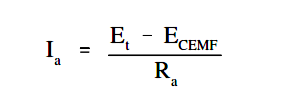
The CEMF opposes the applied voltage and functions to lower armature current. The effective voltage acting in the armature of a motor is the applied voltage, minus the counter EMF. Armature current can be found by using Ohm’s law, as shown in below Equation.

Generator Action in a Motor Formula

where
Ia = armature current
ECEMF == terminal voltage
Et= counter EMF
Ra= armature resistance
Don't Miss Our Updates
Be the first to get exclusive content straight to your email.
We promise not to spam you. You can unsubscribe at any time.
Invalid email address
You've successfully subscribed !

Continue Reading

Calculate Power in Parallel RCL Circuit
Shunt-Wound Motor Operation
AC Induction Motor Slip
4-Wire, Three-Phase Delta Wiring System
Series-Wound Motor
Parallel Circuit Current Calculations
Share This Article
Facebook Whatsapp Whatsapp LinkedIn Copy Link
Share
Leave a Comment

Leave a Reply Cancel reply

Your email address will not be published. Required fields are marked *

Stay Connected

128.3kFollowersLike
69.1kFollowersFollow
210kSubscribersSubscribe
38kFollowersFollow

Categories

Explore More

Impedance in RL Circuits
Series Circuit
Starting of DC Motors
Inductive Time Constant
Multimeter & Megger Principle
Methods of Producing Voltage (Electricity)
Series – Parallel Circuit Analysis
DC Machines Construction

Keep Learning

Voltage and Current Phase Relationships in an Inductive Circuit

Voltage and Current Phase Relationships in an Inductive Circuit

LVR Motor Controller Operation

Low Voltage Protection (LVP) and Low Voltage Release (LVR)

Transformer voltage and turns ratio

Transformer Current Ratio

Simple RC Circuit

Impedance in RC Circuits

Three Phase AC Generators

Three Phase AC Generators

Calculate Power in Series RCL Circuit

Calculate Power in Series RCL Circuit

Generator Action in a Motor

What is Synchroscope ?

What is electrical transformer

Transformer Impedance Ratio

Learn More

Electrical Machines Objective Questions

Electrical Machines MCQ Series 12

Electromagnetic Noise Interference

What is Electromagnetic Noise Interference?

Analog Electronics Objective Questions

Analog Electronics Objective Questions – Set 2

Purge Type Level Transmitter

Purge Type Level Transmitter Questions

Electrical Machines Objective Questions

Electrical Machines MCQ Series 11

Digital Control Systems Multiple Choice Questions

Digital Control Systems Multiple Choice Questions

Hydrostatic interface level measurement Formula

Hydrostatic Interface Level Measurement

solenoid-valves-types-principle-animation

Solenoid Valves Types, Principle & Animation

Menu

  • About
  • Privacy Policy
  • Copyright

Quick Links

  • Learn PLC
  • Helping Hand
  • Part Time Job

YouTube Subscribe

Follow US
All rights reserved. Reproduction in whole or in part without written permission is prohibited.
Welcome Back!

Sign in to your account

Username or Email Address
Password

Lost your password?