To understand just how different FOUNDATION Fieldbus is from other digital instrument systems, consider a typical layout for a distributed control system (DCS), where all the calculations and logical “decisions” are made in dedicated controllers, usually taking the form of a multi-card “rack” with processor(s), analog input cards, analog output cards, and other types of I/O (input/output) cards:
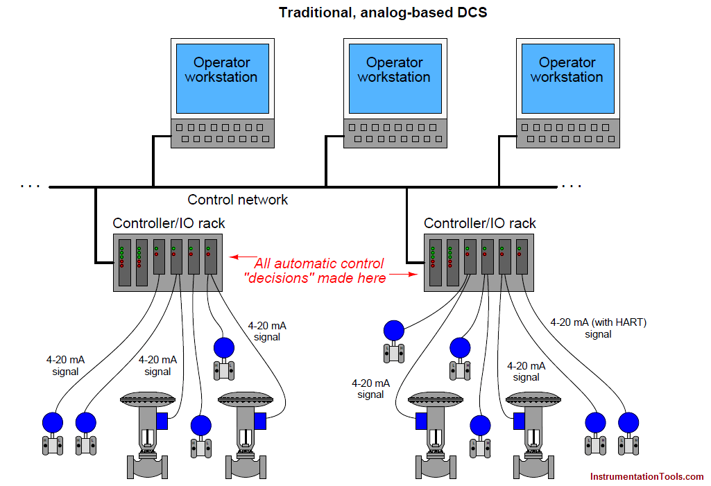
Information is communicated in analog form between the DCS controllers and the field instruments. If equipped with the proper types of I/O cards, the DCS may even communicate digitally with some of the field instruments using HART protocol.
This allows remote configuration and diagnostic testing of field instruments from the host system, or from anywhere along the cable when using a hand-held HART communicator.
It is even possible to build a control system around a DCS using all digital field instruments, using a protocol such as Profibus PA to exchange process variable (PV) and manipulated variable (MV) signals to and from the DCS controllers at digital speeds far exceeding that of HART:
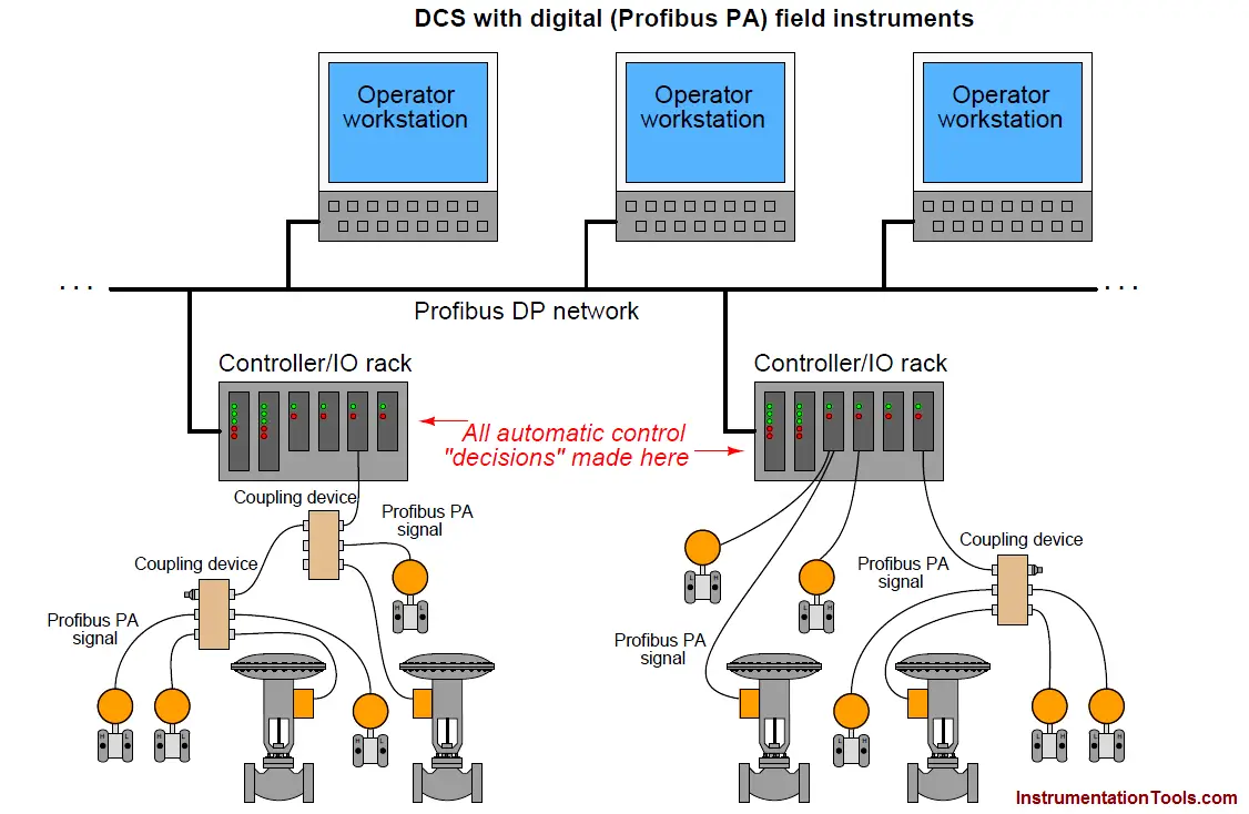
Now, multivariable field instruments have the ability to quickly exchange their data with the DCS, along with maintenance-related information (calibration ranges, error messages, and alarms).
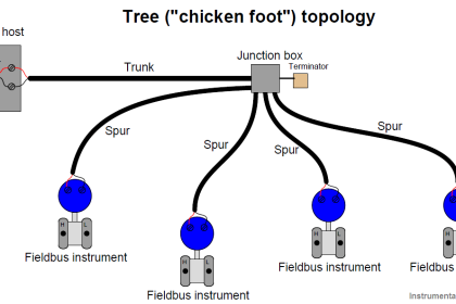
Each “fieldbus” cable is a multi-drop digital network, permitting multiple field devices per cable and consequently reducing total cable length and connection count.
Coupling devices may be used in lieu of terminal blocks to conveniently connect multiple instruments together on common networks leading to the DCS. Still, however, all the automatic control algorithms are implemented in the DCS.
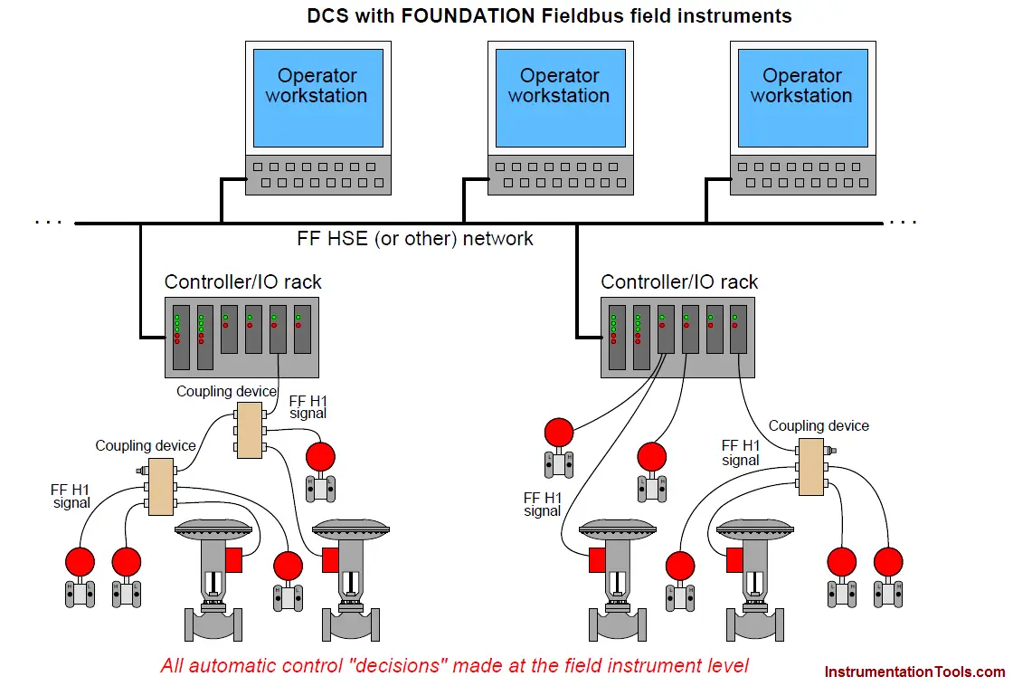
A FOUNDATION Fieldbus system goes one step further by allowing all control algorithms to be executed within the field instruments rather than relying on the DCS controllers to make automatic control “decisions.”
In fact, the DCS would not even be necessary if not for the need of operations personnel to monitor and alter control system status:
Foundation Fieldbus (FF)
That being said, it is possible (and in fact common) for control algorithms to be placed in the DCS controllers in addition to algorithms executed by FF field devices.
The locations of the control algorithms – those microprocessor instructions dictating how the loop will be controlled – in these different systems deserves further elaboration.
To show this, I will make use of function block notation to show where the algorithms are executed in each system type, each function block shown as a yellow box on the diagram.
First, the DCS with analog I/O (inputs/outputs):
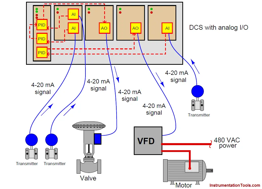
The conversion of 4-20 mA signals from transmitters into a scaled digital number values inside the DCS takes place inside “analog input” (AI) function blocks programmed into the DCS. These converted values then pass to PID function blocks where the arithmetic for control loop decisions takes place.
Finally, the digital output values of the PID blocks get passed on to “analog output” (AO) function blocks where those values are converted back into 4-20 mA analog signals to drive control valves, variable-frequency drives (VFDs), and other final control elements.
Each “function block” is nothing more than a segment of programming code instructing the DCS’s microprocessor what to do with the signal values.
Function blocks are usually selected and arranged by engineers and technicians maintaining the DCS using graphical programming software, allowing function blocks to be placed onto a “palette” and connected with lines to show where their signals come from and go to.
Now let us examine Profibus PA again. Here, the field instruments are entirely digital, communicating with each other via digital signals over a network cable to the DCS.
This means none of the cables carry analog signals anymore, necessitating the A/D and D/A conversion take place inside the field devices themselves.
It also means we may do away with the old analog I/O cards in the DCS rack, replacing them with a single network interface card:
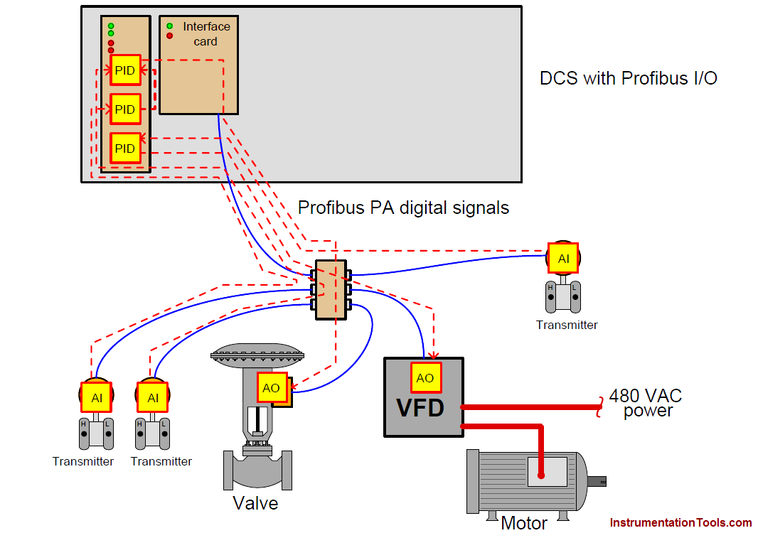
Control decisions still take place within the DCS microprocessor, which is why the PID function blocks are still shown inside the processor card.
The analog-digital signal conversions and scaling operations, however, occur within the field instruments themselves.
Such is the nature of digital networks that multiple instruments may share the same communication cable back to the DCS, with each instrument “taking turns” communicating in time.
FOUNDATION Fieldbus, by contrast, allows even the control decisions to take place within the field devices, unburdening the DCS to perform higher-level tasks as necessary:

With each evolutionary step in system design, the trend has been to “push” the control algorithms further into the field, away from the central control system.
FOUNDATION Fieldbus is the ultimate realization of this trend, where the field instruments themselves can do all necessary control functions.
Here, the only necessary purposes served by the DCS are:
- Initial configuration and maintenance tool for the FF instruments
- Provide operators with an interface allowing indication and adjustment of control parameters
- Record long-term “historical” data on the process being controlled
In fact, given the right FF system design, the DCS could even be disconnected from the FF network, and the FF instruments would continue to control the process as they did before!
This is not to say that all control algorithms must be executed within the field instruments in a FOUNDATION Fieldbus control system.
In fact it is quite common to find FF control systems implemented with the host (DCS) performing most of the control.
FOUNDATION Fieldbus permits but does not mandate that all control tasks reside “in the field”.
When the FF standard was being designed, two different network levels were planned: a “low speed” network for the connection of field instruments to each other to form network segments, and a “high speed” network for use as a plant-wide “backbone” for conveying large amounts of process data over longer distances.
The low-speed (field) network was designated H1, while the high-speed (plant) network was designated H2. Later in the FF standard development process, it was realized that existing Ethernet technology would address all the basic requirements of a high-speed “backbone,” and so it was decided to abandon work on the H2 standard, settling on an extension of 100 Mbps Ethernet called HSE (“High Speed Ethernet”) as the backbone FF network instead.


I like inst tools..very useful..
What is the generalised formula to calculate gas flowing through an orifice?
Instrumentationtools is a very good learning & updating technical knowledge site. I love it.
i need step by step calibration procedure for 4-20 mA flow valve positioner.
there is simple method of calibration. source the mA output up to 25% and set the valve position at 25%. Now set mA value to 20mA and adjust the valve at 100% position. Now stroke the valve position from 0 to 100% to check the calibration. if there is some error at zero position like valve start to move at 5% or 10% signal. so remove this error from feedback link.
Excellent information for refreshing the concepts.
c’est un très bon site pour aider les agents concernée au instrumentation.
Translated from French : it is a very good site to help the agents involved in instrumentation
if HART signal is 4mA-20mA, what signal is FF Protocol using?
Digital signal
good information for basic knowledge and to distinguish different communication protocals in industrial instrumantation and control automation.
no idea