Safety systems are implemented to reduce operational risks and improve process safety; however, there are instances when some signals of this system shall be bypassed or overridden (see the reference articles). Force and Override signals are two common ways to implement such a goal in a Safety System.
Force Versus Override
This article tries to investigate the Force and Override of signals through the examples of facilities presented in some famous systems.

Figure 1: Force and Override Bypassing Signal in Safety System
Signal Bypassing in Safety Systems
Figure 1 shows the main applicable types of signal bypassing in the Safety System. Regardless of direct hardwired jumpering (/ opening) of the signal, Force and Override are two common ways of bypassing the signal in Safety Signal by using the software facilities of the system. We can see that forcing the signal is performed in the System I/O Database, while the Override is implemented within the application program of the project’s functional logic. Therefore, it can be easily concluded that:
Force facility is applicable for all Safety System I/O’s (Inputs and Outputs), while the Override is applicable just for those signals supported by the provided facility (Function Block or arranged Logic Diagram) inside the Application Program.
Furthermore, since an I&C engineer through the Engineering (/Programming) Workstation can change all possible items provided for Input and Output Signals inside the System Database at any time, while changing the application program is not so easy (and may need saving and uploading the program), therefore it can be concluded that:
Adding a Bypass facility for one Safety Signal can be applicable via the Force facility at any time, while it is applicable only during (or by) changing the Application Program (functional logic) via the Override way.
It shall be noticed that the Application Program of the project is provided based on pre-studied process requirements and conditions (and after making exact and complete Process Safety/ Risk management) and so making Safety Signal Bypass through Functional Logic (by Override) has more safety support than in time Process Safety/Risk study by changing the instantaneous value of the signal (by Force). On the other hand, we can say that:
Although bypassing the Safety Signal via Force way, physically is possible or applicable for any input and output signal and at any time, but it will be more risky than the Override way, and needs exact care for obeying legal rules and standard requirements, further to more administrative controls (and possible risks).
However providing Override facility for Bypassing Safety Signal is supported thru studied standard conditions/ requirements (with known estimated risks), that (as the result) are already implemented in Safety System, and hence sequence of execution and monitoring the steps of relevant jobs (and responsibilities) are more controllable than site personnel commitments for obeying administrative rules or procedures (in the Force way).
Sequence of Execution and Monitoring the steps of relevant jobs (and responsibilities) are more controllable via the Override way than the Force way.
In fact, based on defined standard requirements, the Override way is the facility for Device Repair Maintenance or Proof Testing during normal Process Plant Operation, while the Force way is applicable during Process Plant Startup or in the cases of Process Plant Emergency Condition Requests (which for those signals do not have an Override facility), i.e. :
The preferred way of bypassing the Safety Signal is the Override way, and the Force way may be applicable just for those cases that do not have an Override Facility.
Safety System Engineering
Safety System Engineering/ Programming Workstation, is not a whole time running equipment (24 hours a day during Process Plant Operation) and will be used just on the required cases/ times by I&C Engineer. Bypassing Safety Signal is a critical safety item that shall be monitored (/traced) much more than continuous usual process conditions monitoring, since enabling the Bypass will degrade the Safety System and it equals to more safety risks.
So, monitoring the Bypassing Safety Signal shall not depend on the Safety System Engineering Workstation. Focusing on this subject, we may find that the Override way may have better monitoring (indication and alarming) due to the direct connection of HMI Workstations to continuously running Functional Logic and receiving continuous feedback of relevant signals.
Monitoring and Tracing Bypass Signals
On the other hand, monitoring and tracing the Bypassing Signals (during normal plant operation) shall be done via combined Process Control and Safety Systems (including DCS, SIS/ ESD, and HMI Workstations and networks). In order to reach this target, SIS vendors provide different data transfer enhancements, and additionally, Functional Logic Design is done with some more tricks and extra arrangements.
Due to different offered options by System Vendors, bypassing the Safety Signals may be done in different ways, and in some of them, Force way may be done very near to override way. Also, good design considerations make using the Override way bypassing during Process Plant Startup too.
Generally, we can say that:
The performance and completeness of monitoring and tracing the status of Bypassing Safety Signal (via Force or Override) is very dependent on good design and the proposed facilities of Combined Process Control and Safety Systems (including DCS, SID/ESD, and HMI Workstations and networks).
Signal Bypassing (Force and Override) in Some Safety Systems
Although Force and Override Bypassing Safety Signals have some main differences in all available Safety Systems, as mentioned, vendors of such systems may propose some options for presenting different performances. In this article, we just review a brief introduction of some of the famous Safety Systems and their facilities for Force and Override. By such review, we find some of the other characteristics/ specifications of Force and Override as Bypassing the safety Signal.
HIMA ESD SYSTEM
HIMA is one of the famous vendors of Safety Systems, and ELOP-II is the system configurator (programmer) software for such systems. Figure 2 shows a glance at the forcing facility of ELOP-II, and we can find that:
“In the online test, you can force all variables that are defined as physical input or outputs, or local variables that are not overwritten by the program. When an input variable is forced, then this forced value will be used throughout the logic.”
In addition, we can see that ELOP-II has the facility of monitoring the forcing IO in the Force Graphic page as:
“Forcing can be done directly in the logic with the OLT box, or it can be done using the Force graphic in the Control Panel (CP).
…
The Force graphic shows all variables that are combined with an I&C name. The Force graphic consists of the following columns: tag name, data type, Force switch, Force value, variables, and I&C position. You can toggle the Force switch between FALSE and TRUE simply by double-clicking with the mouse. …”
It shall be mentioned that the Override facility for the HIMA system will be provided during the design engineering of the project logic diagram (and considered signal communications with the Process Control System), and according to the applicable requested project specification requirements.

Figure 2: Forcing Facility in HIMA (Safety PLC) Engineering Software.
SIEMENS S7 SYSTEM
SIEMENS also provides Force facility, and in the section “Easy to monitor and test your program”, it was explained about watch tables and force tables, and declares that:
“STEP-7 also provides a force table for “forcing” a tag to a specific value. For more information about forcing, see the section on forcing values in CPU (page 340) in the “Online and Diagnostic” chapter.”
As it can be seen on page 340 of the SIEMENS document, the Forcing can be easily done and monitored by the force table. For the Override facility, similarly, it will be provided during the design engineering of the project logic diagram (and considered signal communications with Process Control System), and according to applicable requested project specification requirements.
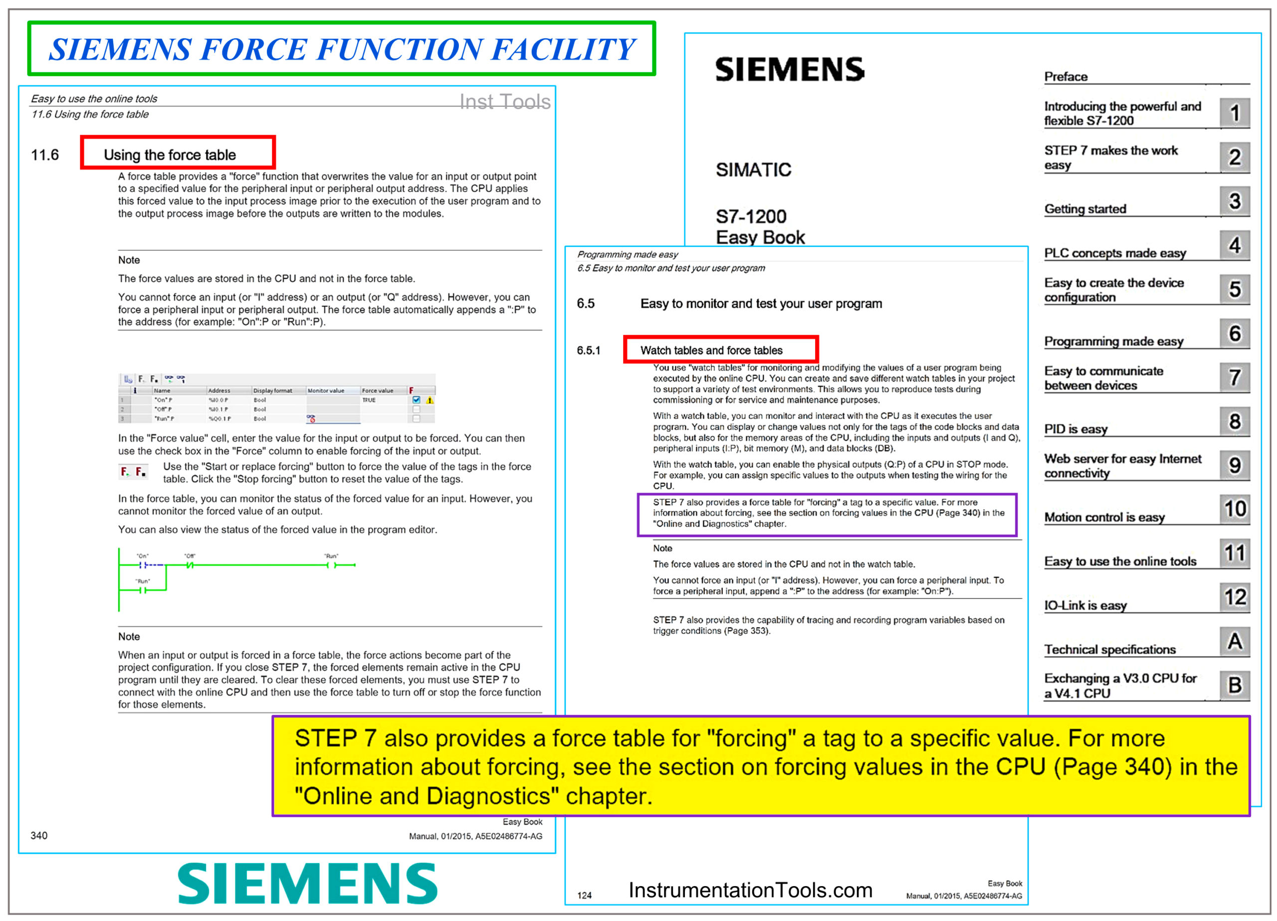
Figure 3: SIEMENS Force Function Facility.
HONEYWELL SYSTEM
Figure 4 shows the forcing facility of the HONEYWELL system, and it can be clearly seen that the effect of applying a forced value is throughout the logic. As it can be seen in Figure 4, the HONEYWELL system shows the list of all forced items too.
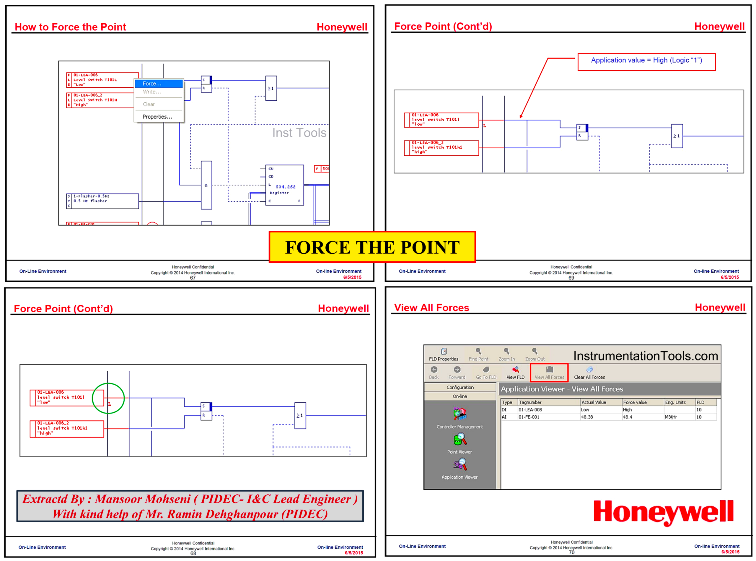
Figure 4: Honeywell Force Function Facility
YOKOGAWA PROSAFE-RS SYSTEM
YOKOGAWA PROSAFE-RS Safety PLC in a combined configuration with CENTUM-CS 3000 provides a combined (Integrated) Process Control and Safety System that provides both Force and predefined Override facilities. As mentioned above, usually override facilities are provided through logic diagram design, while YOKOGAWA offers further predefined function blocks which can be easily inserted in the logic diagram for requested items (Figure 5).
As Figure 6 shows, the Engineering Workstation can do the Force facility, and the Override Function is possible through HMI graphics, while both facilities are monitored via Bypass Monitor:
“This function shows a summary of the forced I/O information and override information, and lists information such as locked variables and overridden tags. It includes information such as the logic solver name and duration of the bypass. This information can be exported in a CSV format for easy integration with other software packages for report generation and/ or dashboard display purposes.”

Figure 5: Yokogawa Override Function Facility
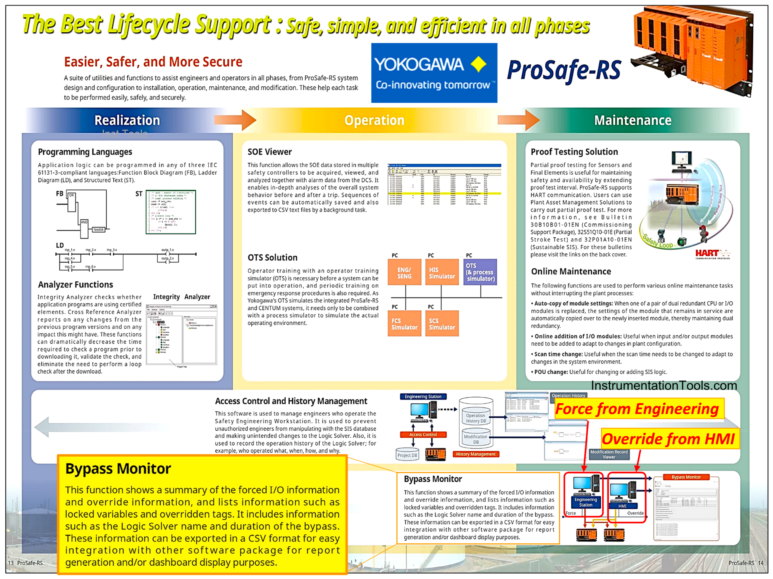
Figure 6: Yokogawa Prosafe-RS Bypass Monitor Facility
Although YOKOGAWA provides both Forcing and Override Facilities for Prosafe-RS, the differences between the two facilities are clarified in the document too (Figure 7).
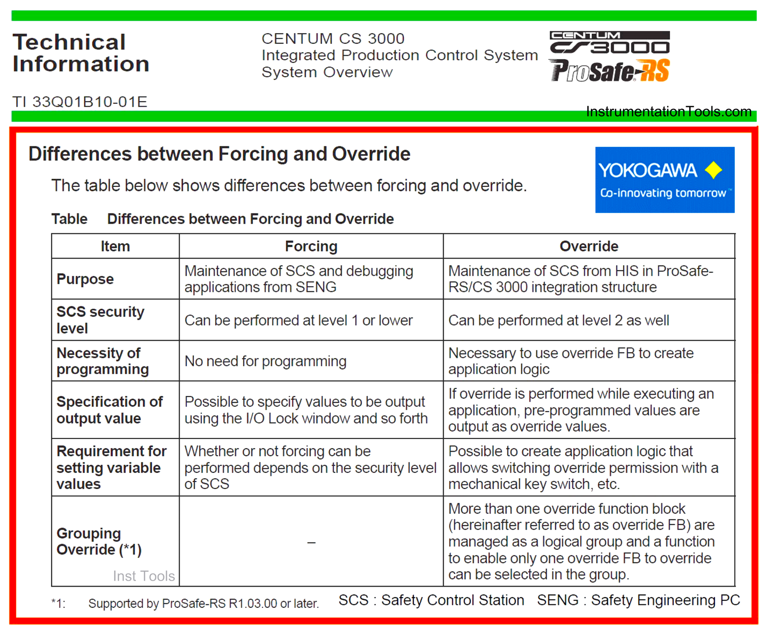
Figure 7: Differences between Forcing and Override in Yokogawa Prosafe-RS
As it is clear from the purpose difference, Override is implemented in the integration of Prosafe-RS with the CS-3000 structure. In fact, the Override facility will be more regular and informative, so that it can be used by higher-level process management software like Exaquantum/ OSA (Override Safety Advisor) for improving safety and operator performance. Some of the advantages of hiring OSA can be found in Figure 8.
Reviewing such good facilities and improvements shows that hiring of OSA may increase the effectiveness of Process Safety Management (or its element Process Bypass Management) to the near possible highest level. Process Bypass Management uses the bypass facility provided by the combined Process Control and Safety System as a core facility/ activity and increases the relevant safety (or accordingly minimizes the possible risks) by administrative controls (procedures, rules, process hazard analysis, sequence of activities, responsibility charts, defined authorization levels, action plan/ list, …).
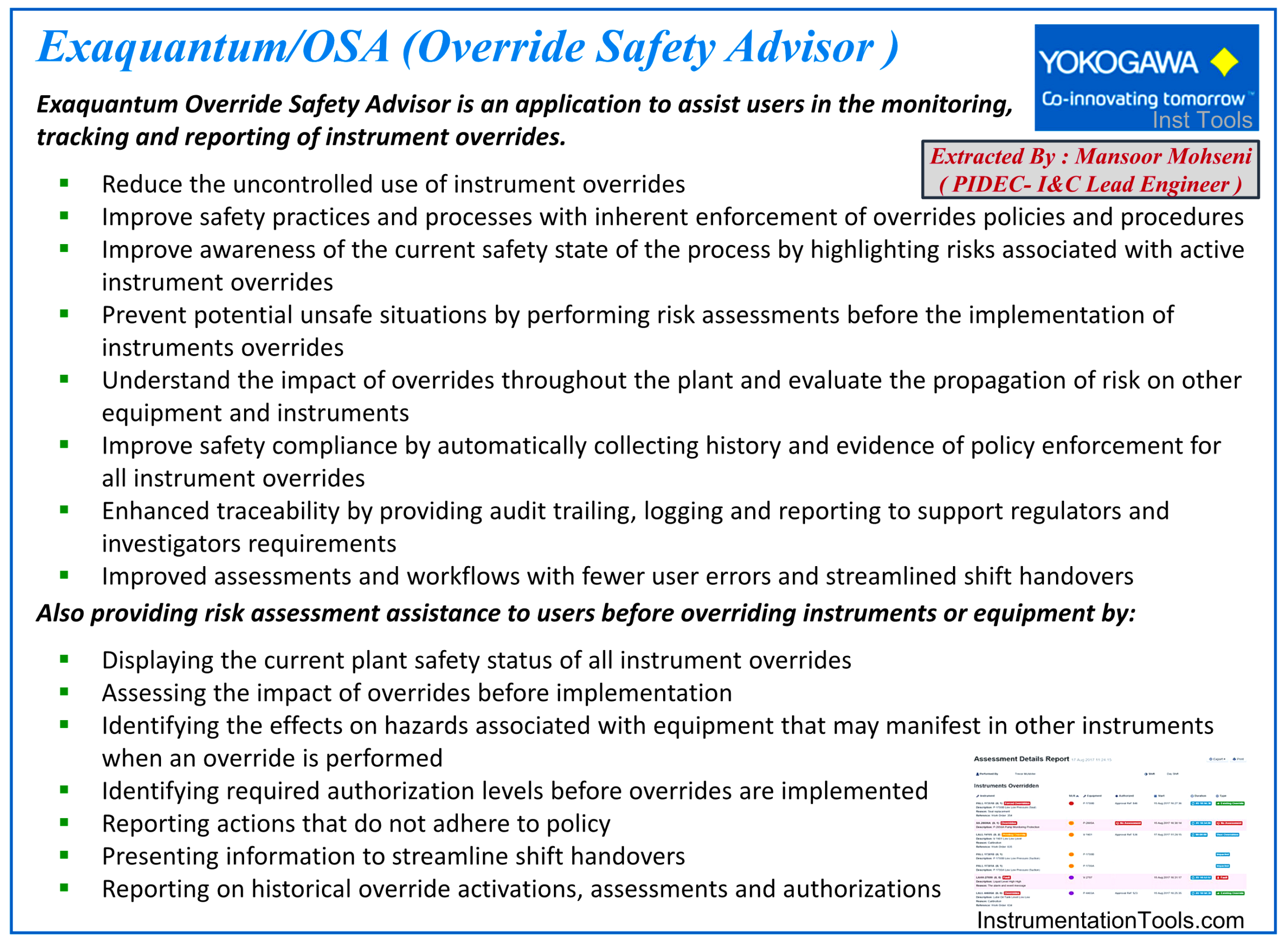
Figure-8: Yokogawa Exaquantum/ OSA (override Safety Advisor)
Conclusion
Forcing and override facilities are two ways for Bypassing Safety Signals via hiring Safety System Software. Forcing facility is implemented in the I/O database, while the Override facility is provided directly throughout the Safety System Logic Diagram (/Application Program), further to transferring data with Process Control System (including HMI).
In fact, the Override facility may be considered as more informative, regular, and effective, and if it is properly combined with administrative controls (or even higher software tools), it can produce the most effective Process Bypass Management.
References:
- Safety Function Bypass or Override
- IEC 61511 Standard for Bypass & Override
- Types of Implementing Safety Signal Bypass
- A Good Practice on Override Safety Signal
- Safety Bypass Management System


very nice instrumentation subject Sir thank you