Rangeability is usually defined as the ratio of maximum to minimum flow the transmitter can measure.
There are two definitions of “maximum flow” which are commonly used in specifying the rangeability of a flow meter. It is important to understand the difference between the two methods of defining the maximum flow because it can mean the difference between a flow meter that can measure the flow range of interest and one that can’t.
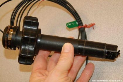
Flow Transmitter Rangeability

The first way to define “maximum flow” is the maximum flow rate that the flow meter can measure. This means the maximum capacity of a flow transmitter that measures. This is how most flow meters specify rangeability in product literature.
The other way to define the “maximum flow” is the maximum flow rate that occurs in a particular application. This means as per your present application or installation or process conditions, the maximum flow that transmitters measure in the pipeline (This flow must be less when compared to the transmitter’s maximum capability). This is how most DP flow meters are specified. DP rangeability is always referred to from the application’s maximum flow.
The distinction is critical because the specified meter maximum is often 2 to 3 times the application maximum. Generally chosen Flow Transmitter’s maximum sensing flow rate is always more than the process maximum flow rate.
Rangeability Example
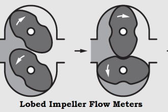
For example: In liquid applications, Vortex, Coriolis, Magnetic, and Ultrasonic flowmeters are designed to measure maximum flow rates of 20-30 ft/sec. The optimum economic flowing velocity for liquids is about 5-6 ft/second, and they rarely flow over 10 ft/sec.
That means that a flow meter with a 20 or 30:1 flow rangeability from meter maximum, typically measures less than a 10:1 flow range in most actual processes. For gas applications, meter maximum flows are also much higher than typical process maximum flows.
To achieve the meter maximum flow and rangeability in a typical application, pipe size must be reduced at the meter.
This increases installation costs and permanent pressure loss, which may not be acceptable for some applications. For this reason, flow meter rangeability should be considered from the application maximum or process flow maximum, not the meter’s maximum specified flow rate.
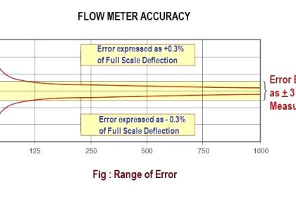
It is also important to understand how the max-to-min flow ratio relates to the percent of the flow range.
The figure shows the relationship between rangeability and percent of maximum flow. Notice that 10:1 rangeability will measure down to 10% of maximum flow. A meter with 20:1 rangeability will measure down to 5% of maximum flow; only 5% more of the flow range.
Since a meter with a high rangeability can significantly increase the cost, care should be taken to specify no more rangeability than will actually be required in a particular application.
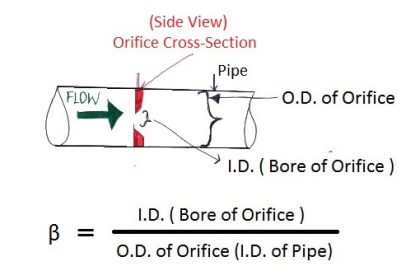
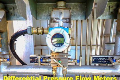
The orifice plate has traditionally been regarded as having a maximum rangeability of 3:1 or 4:1. This comes from the pneumatic transmitter days when the transmitter limited the measurement range. With a properly selected orifice and a modern DP transmitter, a rangeability of 5:1 to as high as 14:1 is certainly possible.
Combining this multivariable rangeability with the ability to interchange orifice plates, a flow range of 200:1 can be measured without changing the pipe size or the transmitter.
For example, if a meter can measure from 150 m3/day to 300 m3/day, then the rangeability is 300/150 which is 2/1 when reduced to its lowest common denominator. The volume a meter can measure changes as operating pressure and temperature change. Although the theoretical rangeability can increase, in practice the rangeability usually decreases.
To calculate the minimum expected rangeability the operating pressure and temperature range must be determined. Use the minimum pressure, maximum temperature, and maximum meter output to calculate the lowest maximum flow rate.
The opposite combination of maximum pressure, minimum temperature, and minimum meter output is used to calculate the highest minimum flow rate. If composition varies significantly it needs to be factored into reducing the maximum flow rate and increasing the minimum flow rate.
Rangeability for ultrasonic, turbine, and RD meters is extremely important because the metering capability cannot be changed by changing the meter. Under-sizing of the meter results in accuracy problems in ultrasonic meters and accuracy/damage of turbine and PD meters. To avoid this problem the meters are usually sized with a maximum metering capability less than the maximum output.
Reference – Emerson
If you liked this article, then please subscribe to our YouTube Channel for Instrumentation, Electrical, PLC, and SCADA video tutorials.
You can also follow us on Facebook and Twitter to receive daily updates.
Read Next:
- Turbine Flow Meter Principle
- What is a Flow Nozzle?
- 4-20 mA from Process Variable
- Questions on Flow Sensors
- Cone Flow Meter Operation


Sir How to check rangeability for DP type Level transmitter.
This article makes an excellent point. The theoretical turndown of a flow meter should never be used as part of the specification because it may not be usable for the particular fluid velocities in your application.
In my opinion, incorrectly sized flow meters are the cause of large errors in flow readings. Selecting the correct flowmeter or having a dp flow element manufactured for your exact requirements is often more cost effective in the long run than a poorly sized “off the shelf” flow meter that promised unuseable turndown.