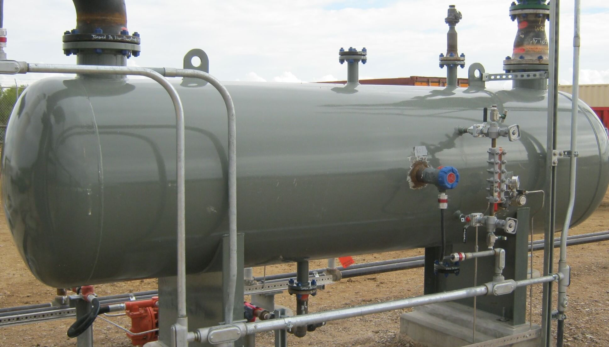
Inst ToolsInst ToolsInst Tools
  • Courses
  • Automation
    • PLC
    • Control System
    • Safety System
    • Communication
    • Fire & Gas System
  • Instrumentation
    • Design
    • Pressure
    • Temperature
    • Flow
    • Level
    • Vibration
    • Analyzer
    • Control Valve
    • Switch
    • Calibration
    • Erection & Commissioning
  • Interview
    • Instrumentation
    • Electrical
    • Electronics
    • Practical
  • Q&A
    • Instrumentation
    • Control System
    • Electrical
    • Electronics
    • Analog Electronics
    • Digital Electronics
    • Power Electronics
    • Microprocessor
  • Request
Search
  • Books
  • Software
  • Projects
  • Process
  • Tools
  • Basics
  • Formula
  • Power Plant
  • Root Cause Analysis
  • Electrical Basics
  • Animation
  • Standards
  • 4-20 mA Course
  • Siemens PLC Course
Reading: Flare Knockout Drums Working Animation
Share
Notification Show More
Font ResizerAa
Inst ToolsInst Tools
Font ResizerAa
  • Courses
  • Design
  • PLC
  • Interview
  • Control System
Search
  • Courses
  • Automation
    • PLC
    • Control System
    • Safety System
    • Communication
    • Fire & Gas System
  • Instrumentation
    • Design
    • Pressure
    • Temperature
    • Flow
    • Level
    • Vibration
    • Analyzer
    • Control Valve
    • Switch
    • Calibration
    • Erection & Commissioning
  • Interview
    • Instrumentation
    • Electrical
    • Electronics
    • Practical
  • Q&A
    • Instrumentation
    • Control System
    • Electrical
    • Electronics
    • Analog Electronics
    • Digital Electronics
    • Power Electronics
    • Microprocessor
  • Request
Follow US
All rights reserved. Reproduction in whole or in part without written permission is prohibited.
Inst Tools > Blog > Animation > Flare Knockout Drums Working Animation

Flare Knockout Drums Working Animation

Last updated: March 14, 2018 6:53 am
Editorial Staff
Animation How It Works Process
3 Comments
Share
2 Min Read
SHARE

KNOCK OUT DRUMS

Flare Knockout Drums Working Animation

Knock out vessels are used to slow down gasses and allow liquids to “fall out” of the gas stream. Knock out drums can be installed either in the waste gas header, or in the flare stack base itself. Knock out drums can be configured in either a horizontal, or vertical arrangement. When horizontal, a knock out drum will be constructed with one gas stream inlet, and two outlets, which can then be joined with a manifold. Another configuration that can be used is one inlet with a much larger outlet.

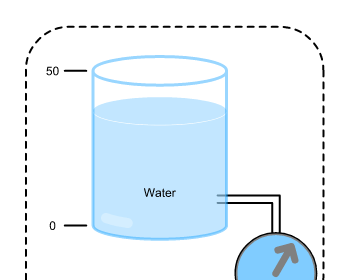
A liquid level gauge or indicator should always be included, as these vessels must remain drained and free of excess liquid. In a vertical arrangement the knock out drum can have a side inlet with a larger exit which will slow down the gasses. Another method for using a vertical drum is to use a tangential inlet. With a tangential knock out drum, the gasses enter and spin around the wall of the vessel. While spinning the fluidic friction of the gas along the wall will “scrub out” much of the entrained liquid.

Flare KOD

Baffles are also used in a vertical drum to disrupt and slow down the gas prior to exit. Again these drums must be equipped with a liquid level gauge or indicator so they can be drained. Knock out drums, whether installed in the waste gas header, or in the flare base can be supplied with the following options: Vessels are sized according to clients’ process requirements. Construction can be of Carbon Steel, or for corrosive services Stainless steel. Automatic drain controls can be included to prevent the accumulation of fluids in the seal. Two-inch flanged drain connection for draining and cleaning the vessel.

Also Read: Process Fundamentals in Oil & Gas Industries

Don't Miss Our Updates
Be the first to get exclusive content straight to your email.
We promise not to spam you. You can unsubscribe at any time.
Invalid email address
You've successfully subscribed !

Continue Reading

Thermistor Working Principle
Thermocouple Working Principle
Strain Gauge Animation
What is EDI in a Water Treatment Plant? – Electro deionization
Float Level Switch Working Principle Animation
Pressurizer
Share This Article
Facebook Whatsapp Whatsapp LinkedIn Copy Link
Share
3 Comments
  • Wallis says:
    November 9, 2015 at 10:31 pm

    Helpful instrumentation documents. I have learnt more than I knew. Thanks to everyone who have contributed to this website.

    Reply
  • sapna says:
    August 18, 2016 at 10:35 am

    wonderfull site..most importantly its explained in very simple words

    Reply
  • Uduemor Dominic says:
    November 15, 2017 at 11:05 am

    very informative article.

    Reply

Leave a Reply Cancel reply

Your email address will not be published. Required fields are marked *

Stay Connected

128.3kFollowersLike
69.1kFollowersFollow
210kSubscribersSubscribe
38kFollowersFollow

Categories

Explore More

Swirl Flow Meters Working Principle
PID Controller Gains Effect on Manipulated Variable
Cartridge Filters
Rotary Abutment Flow Meters Working Principle and Animation
How a Level Switch Works
Control Valve Working Animation
Process Design of Instrument Air System
Vibrating Tube Densitometers Working Principle

Keep Learning

swing check valve Theory

Hydraulic System

four-way-solenoid-valve-diagram

Four Way Solenoid Valve Working Principle

Why counter-current heat exchangers are better than co-currents?

Why Counter-current Heat Exchangers are better than Co-current?

Y Strainer

What is a Y Strainer ?

Electrical Circuit Label Schematic

Label the Electrical Circuit Schematic

PLC Latching circuit Animation

What is Seal-in Circuit ?

Flame Arrester Principle

Flame Arrester Principle

Plant Air Storage Tank

Plant Air Storage Tank Pressure Fluctuations Root Cause Analysis

Learn More

Comparison of Flowmeters

Difference between Different Types of Flow Meters

Introduction to SCL Programming in Siemens PLC

Types of Expressions in the SCL Language of the Tia Portal

Retentive Timer (RTO)

Timer in Studio 5000 – TON, TOF, RTO

Transistor Stabilisation

Transistor Stabilisation

seven-segment-display-circuit

Seven Segment Display Working Principle

Analog inputs in library

Design Process Graphics in Factory Talk View Studio with an Analog Input

Single-element drum level control system

Single Element Drum Level Control System

SIS PFD - Safety Instrumented System

SIS PFD – Safety Instrumented System

Menu

  • About
  • Privacy Policy
  • Copyright

Quick Links

  • Learn PLC
  • Helping Hand
  • Part Time Job

YouTube Subscribe

Follow US
All rights reserved. Reproduction in whole or in part without written permission is prohibited.
Welcome Back!

Sign in to your account

Username or Email Address
Password

Lost your password?