Inst ToolsInst ToolsInst Tools
  • Courses
  • Automation
    • PLC
    • Control System
    • Safety System
    • Communication
    • Fire & Gas System
  • Instrumentation
    • Design
    • Pressure
    • Temperature
    • Flow
    • Level
    • Vibration
    • Analyzer
    • Control Valve
    • Switch
    • Calibration
    • Erection & Commissioning
  • Interview
    • Instrumentation
    • Electrical
    • Electronics
    • Practical
  • Q&A
    • Instrumentation
    • Control System
    • Electrical
    • Electronics
    • Analog Electronics
    • Digital Electronics
    • Power Electronics
    • Microprocessor
  • Request
Search
  • Books
  • Software
  • Projects
  • Process
  • Tools
  • Basics
  • Formula
  • Power Plant
  • Root Cause Analysis
  • Electrical Basics
  • Animation
  • Standards
  • 4-20 mA Course
  • Siemens PLC Course
Reading: Fisher model 546 I/P transducer
Share
Font ResizerAa
Inst ToolsInst Tools
Font ResizerAa
  • Courses
  • Design
  • PLC
  • Interview
  • Control System
Search
  • Courses
  • Automation
    • PLC
    • Control System
    • Safety System
    • Communication
    • Fire & Gas System
  • Instrumentation
    • Design
    • Pressure
    • Temperature
    • Flow
    • Level
    • Vibration
    • Analyzer
    • Control Valve
    • Switch
    • Calibration
    • Erection & Commissioning
  • Interview
    • Instrumentation
    • Electrical
    • Electronics
    • Practical
  • Q&A
    • Instrumentation
    • Control System
    • Electrical
    • Electronics
    • Analog Electronics
    • Digital Electronics
    • Power Electronics
    • Microprocessor
  • Request
Follow US
All rights reserved. Reproduction in whole or in part without written permission is prohibited.
Inst Tools > Blog > Practical Questions > Fisher model 546 I/P transducer

Fisher model 546 I/P transducer

Suppose this Fisher model 546 I/P transducer has an input range of 4-20 mA and an output range of 3-15 PSI.

Last updated: October 1, 2020 5:30 pm
Editorial Staff
Practical Questions
No Comments
Share
2 Min Read
SHARE

Suppose this Fisher model 546 I/P transducer has an input range of 4-20 mA and an output range of 3-15 PSI:

Fisher model 546 I/P transducer

Fisher model 546 I to P transducer

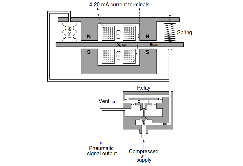
Note: This is an old model, now many smart I/P converters available n the market.

Identify which way the magnetic shunt would have to be moved in order to re-calibrate the I/P transducer to a new output range of 4-20 PSI (from 3-15 PSI), explaining your reasoning.

Identify which way the zero screw would have to be turned in order to re-calibrate the I/P transducer to a new output range of 2-14 PSI (from 3-15 PSI), explaining your reasoning.

Answer:

Move the magnetic shunt further out in order to re-calibrate from 3-15 PSI to 4-20 PSI.

Turn the zero screw so the spring doesn’t push down as hard on the right-hand side of the beam in order to re-calibrate from 3-15 PSI to 2-14 PSI.

More Questions

1. What would happen if some of the turns in the electromagnet coil were shorted past? Would this cause a zero shift, a span shift, or a linearity shift?

2. What would happen if the zero spring broke into two separate pieces? Would this cause a zero shift, a span shift, or a linearity shift?

3. Suppose this I/P outputs a pressure of 9.0 PSI at an input current of 12.3 mA. Calculate the error, in percent of span.

4. Suppose this I/P outputs a pressure of 12.5 PSI at an input current of 16.0 mA. Calculate the error, in percent of span.

5. Suppose this I/P outputs a pressure of 5.7 PSI at an input current of 8.0 mA. Calculate the error, in percent of span.

Share your answers with us through the below comments section.

Read Next:

  • DP Transmitter Problem
  • Pressure Gauge Datasheet
  • Temperature Controller Problem
  • Pressure Measurement MCQ
  • Pressure Transmitter Manifold

Credits: Tony R. Kuphaldt

Don't Miss Our Updates
Be the first to get exclusive content straight to your email.
We promise not to spam you. You can unsubscribe at any time.
Invalid email address
You've successfully subscribed !

Continue Reading

Double Block and Bleed Valves Opening or Closing Sequence
Calculate Hydraulic Pressure of a Process Vessel
How much Pressure is applied to Inclined Water Manometer?
Determine the Problems with Level Transmitter and Gauge
Air Pressure Inside the Tank
Liquid Level Measurement using Pressure Transmitter Questions
Share This Article
Facebook Whatsapp Whatsapp LinkedIn Copy Link
Share
Leave a Comment

Leave a Reply Cancel reply

Your email address will not be published. Required fields are marked *

Stay Connected

128.3kFollowersLike
69.1kFollowersFollow
210kSubscribersSubscribe
38kFollowersFollow

Categories

Explore More

Three-valve Manifold on Remote Seal DP Transmitter
Problem with Sump Tank Level Transmitter
What is the Purpose of Chemical Seals Pressure Transmitter?
Questions on Pressure Transmitter Calibration Setup
Liquid Flow Control Loop Controller Action
Problem on Solar Hot Air Collector and Variable Speed Fan
Determine Calibration Range of Pneumatic Pressure Transmitter
Programmable Logic Controller (PLC) Questions and Answers – 5

Keep Learning

Pressure Transmitter Re-Range Questions

Pressure Transmitter Re-Range Questions

simulate a thermocouple

Calculate the appropriate millivoltage values of a Thermocouple

Level-Measuring-Instruments-Velocities-of-Propagation

Level Measuring Instruments Velocities of Propagation

Float-type Level Switch for Sensing Low Oil Level

Float-type Level Switch for Sensing Low Oil Level

What Effect on Hydrostatic Level Transmitter if Liquid Density Changes?

What Effect on Hydrostatic Level Transmitter if Liquid Density Changes?

Calibration setup for a low-range electronic pressure transmitter

Instrument Lab Exercise – Ranging and Manometer Usage

Determine the Pressure at Each Port of DP Transmitter

Determine the Pressure at Each Port of DP Transmitter

PLC Circuit Answers

PLC connected to Three Pushbutton Switches

Learn More

7 OSI Layers of Communications

7 OSI Layers of Communication

Electrical Machine Design Objective Questions and Answers

150+ Electrical Machine Design Objective Questions and Answers

PLC Questions & Answers

Programmable Logic Controller Questions and Answers

Instrument Cable

Difference Between Power Cable and Instrument Cable

Two wire loop powered transmitters

4-20 mA Transmitter Wiring Types : 2-Wire, 3-Wire, 4-Wire

PLC Load Memory

What is Resources Tab in the Siemens PLC?

Ladder Diagram Example using Memory Bits and Set Coils

Ladder Diagram Example using Memory Bits and Set Coils

Control Loops Multiple Choice Questions

Control Loop Multiple Choice Questions

Menu

  • About
  • Privacy Policy
  • Copyright

Quick Links

  • Learn PLC
  • Helping Hand
  • Part Time Job

YouTube Subscribe

Follow US
All rights reserved. Reproduction in whole or in part without written permission is prohibited.
Welcome Back!

Sign in to your account

Username or Email Address
Password

Lost your password?