Inst ToolsInst ToolsInst Tools
  • Courses
  • Automation
    • PLC
    • Control System
    • Safety System
    • Communication
    • Fire & Gas System
  • Instrumentation
    • Design
    • Pressure
    • Temperature
    • Flow
    • Level
    • Vibration
    • Analyzer
    • Control Valve
    • Switch
    • Calibration
    • Erection & Commissioning
  • Interview
    • Instrumentation
    • Electrical
    • Electronics
    • Practical
  • Q&A
    • Instrumentation
    • Control System
    • Electrical
    • Electronics
    • Analog Electronics
    • Digital Electronics
    • Power Electronics
    • Microprocessor
  • Request
Search
  • Books
  • Software
  • Projects
  • Process
  • Tools
  • Basics
  • Formula
  • Power Plant
  • Root Cause Analysis
  • Electrical Basics
  • Animation
  • Standards
  • 4-20 mA Course
  • Siemens PLC Course
Reading: How to Filter Digital and Analog Inputs in a PLC?
Share
Font ResizerAa
Inst ToolsInst Tools
Font ResizerAa
  • Courses
  • Design
  • PLC
  • Interview
  • Control System
Search
  • Courses
  • Automation
    • PLC
    • Control System
    • Safety System
    • Communication
    • Fire & Gas System
  • Instrumentation
    • Design
    • Pressure
    • Temperature
    • Flow
    • Level
    • Vibration
    • Analyzer
    • Control Valve
    • Switch
    • Calibration
    • Erection & Commissioning
  • Interview
    • Instrumentation
    • Electrical
    • Electronics
    • Practical
  • Q&A
    • Instrumentation
    • Control System
    • Electrical
    • Electronics
    • Analog Electronics
    • Digital Electronics
    • Power Electronics
    • Microprocessor
  • Request
Follow US
All rights reserved. Reproduction in whole or in part without written permission is prohibited.
Inst Tools > Blog > PLC Tutorials > How to Filter Digital and Analog Inputs in a PLC?

How to Filter Digital and Analog Inputs in a PLC?

A filter is used to remove unwanted spikes and fluctuations in the analog and digital input signals received in a PLC.

Last updated: September 28, 2022 4:14 pm
Viral Nagda
PLC Tutorials
No Comments
Share
5 Min Read
SHARE

In this post, we will understand how to filter digital and analog inputs in a PLC.

Contents
PLC Digital Input FiltersPLC Analog Input Filters

As the topic says, filtering is a means to remove unwanted spikes in the signals received in PLC. Its role is to eliminate the fluctuations and pass only proper signal changes at a particular time to the PLC.

Inside a PLC, the filter circuitry comes first and then comes the PLC input processing circuitry, which accepts the final filtered input and uses it for its logic.

How to Filter Digital and Analog Inputs in a PLC

PLC Digital Input Filters

Let us first consider the digital input. The role of input with a filter is to accept a digital field input and pass it to a processing circuit through the filter.

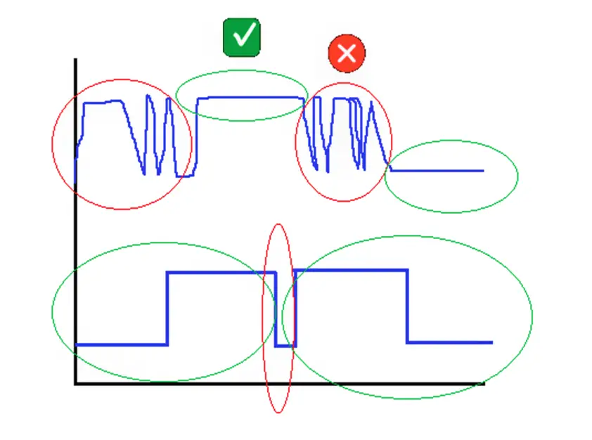
If you see the below image, there are two parts.

First of all, the green circle indicates that the input change will be passed and the red circle shows that the input change will not be passed.

In the first (above) part, there are two changes where there are many fluctuations and that input changes will be bypassed.

There are two changes where there are no fluctuations and that input change will be passed to the processing circuit. The same is the theory with the second (below) part. This is possible by filtering.

PLC Digital Input Filters

Filtering is defined by a factor or time. Suppose you set a time of 3 ms. The role of the filter is to accept only that input change that stays higher than 3 ms.

If the input changes before 3 ms, then that input will not be considered and will be ignored. This means that short and high-frequency interference pulses will be neglected.

This logic is the same as a debounce timer that we write in the PLC logic.

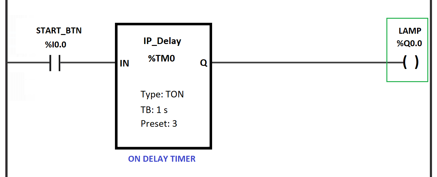
In the below image, the lamp will turn on only when the start button input remains high for 3 seconds.

This is the same logic used in a digital pass filter. It will pass on the input change to the processing part only when that input maintains a state (high or low) for the set time.

Debounce timer in PLC logic

Apart from time, as discussed, some PLCs have the option of setting a factor instead of time.

The factor calculates the internal time and decides the level of filtering. Higher the factor value, the higher the filtering power.

PLC Analog Input Filters

Now, let us see the filtering in analog inputs. As analog inputs are variable in nature, the filter logic for them cannot be implemented the same as for digital inputs.

So, in analog inputs, averaging logic is used. The filter will average the values attained in a particular set time and give an average final value for that time.

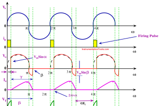
Refer to the below image for the study.

PLC Analog Input Filters

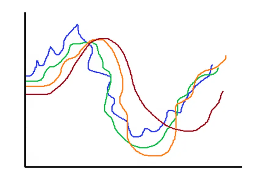
The first one – the blue color has a factor of 1.

The second one – the green color has a factor of 2.

The third one – the orange color has a factor of 3.

The fourth one – the brown color has a factor of 4.

As the value of the filter factor increases, you can see that the shape of the signal improves by filtering the signal at a sharper value.

In a set time, the filter will average the values that it gets from the input; and based on formulas used inside it, it will give the final average output per time.

So, as the filter factor or weightage is increased, we get a finer value of an analog signal with less interference. Normally, a first-pass filter is used for this purpose.

In this way, we conclude that filtering is of great use in reducing unwanted noise from the field input and passing proper values, which will also protect the PLC input circuit from damage; if any high or unwanted spikes occur.

If you liked this article, then please subscribe to our YouTube Channel for Instrumentation, Electrical, PLC, and SCADA video tutorials.

You can also follow us on Facebook and Twitter to receive daily updates.

Read Next:

  • What is a Safety Relay?
  • List of PLC Spares
  • Push button PLC Logic
  • Siemens Timer Value
  • Allen Bradley Architecture
Don't Miss Our Updates
Be the first to get exclusive content straight to your email.
We promise not to spam you. You can unsubscribe at any time.
Invalid email address
You've successfully subscribed !

Continue Reading

Documentation and Change Control of PLC or DCS Systems
Hardware Troubleshooting Steps for PLC Automation Systems
SCADA Interview Questions and Answers
What is Live Zero in 4-20 mA Current Loop?
Various Types of Delta PLC used in Industrial Automation
Relay circuits
Share This Article
Facebook Whatsapp Whatsapp LinkedIn Copy Link
Share
Leave a Comment

Leave a Reply Cancel reply

Your email address will not be published. Required fields are marked *

Stay Connected

128.3kFollowersLike
69.1kFollowersFollow
210kSubscribersSubscribe
38kFollowersFollow

Categories

Explore More

Shift Bit Register in PLC
Factory Acceptance Test (FAT) of a PLC Panel
Types of SCADA System Architecture
What are Faceplates? How to Create a Faceplate? HMI Visualization
Procedure for Connecting Allen Bradley PLC and PC – RS Logix 500
Conveyor Sorting Machine PLC Program with Calculation Function
How to Work With Simulator in S7-1200 and S7-1500 PLC?
Types of Expressions in the SCL Language of the Tia Portal

Keep Learning

Basics of Sinking and Sourcing

Basics of Sinking and Sourcing – Automation System MCQ

Forward reverse motor control diagram with timer

Timer during Motor Direction Change PLC Program

PLC Programmer Salary and Future Career Scope

PLC Programmer Salary and Future Career Scope

Distributed IO for Siemens PLC

How to Configure Distributed IO in a PLC Project?

PLC Stop - Start Circuit

Introduction to PLC Ladder Diagrams

Electrical Ladder Diagram Control using Timers Example

Electrical Ladder Diagram Control using Timers Example

Read Temperature in PLC

PLC Program to Read Temperature in PLC

Open Loop and Closed Loop System Questions

Open Loop and Closed Loop System Questions Answers

Learn More

Difference Between Overcurrent and Overload

Difference Between Overcurrent and Overload

List of 100 Industrial Instrumentation Questions

List of 300 Industrial Instrumentation Questions

Capacitive Pressure Transducer

Capacitive Type Pressure Transducers Principle

Electrical Machines Questions and Answers

Double Excited Magnetic System Quiz

Hydrostatic interface level measurement Formula

Hydrostatic Interface Level Measurement

2 wire transmitter current loops

2-wire Transmitters Current Loops

Advantages and Disadvantages of Network Topology

Advantages & Disadvantages of Different Vibration Sensors

HMI screen for operator

#8 PLC Best Practices – Validate HMI Input Variables at PLC Level

Menu

  • About
  • Privacy Policy
  • Copyright

Quick Links

  • Learn PLC
  • Helping Hand
  • Part Time Job

YouTube Subscribe

Follow US
All rights reserved. Reproduction in whole or in part without written permission is prohibited.
Welcome Back!

Sign in to your account

Username or Email Address
Password

Lost your password?