Fiber Optic Sensing Applications
Optical fibers find applications beyond electronic data cable replacement, though, which means they will be a growing presence in the field of industrial instrumentation above and beyond their use as serial data communication cables. Some industrial process transmitters use optical fibers to send and receive light between the transmitter electronics and an optically-based primary sensing element. This may be as simple as a non-contact proximity switch using light to sense the presence of an object within a gap between the two fibers’ ends, or as sophisticated as a chemical analyzer relying on the absorption of specific light wavelengths to detect the presence of a chemical substance in a solution.
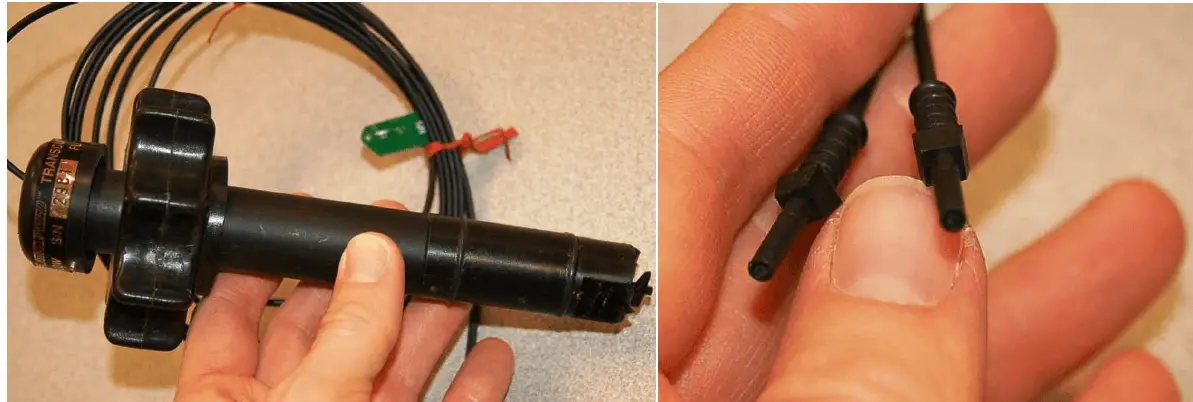
Turbine flowmeter sensing
One example of a specialized application for optical fibers is shown in this photograph of a paddlewheel-style liquid flowmeter using a pair of optical fibers to convey light to and from the paddlewheel assembly, where the spinning paddle wheel serves to “chop” the light beam and thereby represent liquid flow rate as a frequency of pulsing light:
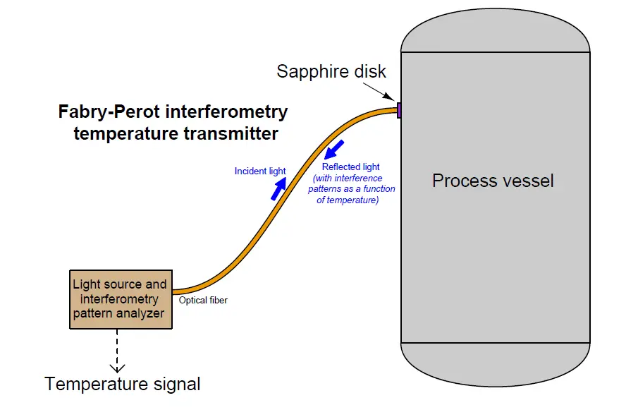
Fabry-Perot interferometry temperature measurement
Another example of a specialized application for optical fibers is measurement of high temperatures using the Fabry-Perot interferometry method. This technology utilizes a small, thin disk of sapphire as a temperature sensor. The thickness of this disk as well as the speed of light through the sapphire are both temperature-dependent, which means a photon of light shot at the face of the disk will reflect off the back face of the disk and return to the source at different times depending on the temperature of the disk. In a Fabry-Perot interferometer instrument, the “optical thickness” of the sapphire disk is measured by sending a continuous beam of white light to the disk and receiving the reflected light from the disk through a single optical fiber, the optical interference resulting from the incident and reflected light beams representing the disk’s temperature. This novel method of temperature measurement shows promise for certain challenging industrial process applications such as high-temperature measurement inside slagging coal gasifiers used to efficiently extract energy and chemical feedstocks from coal:
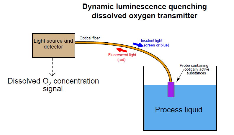
Dissolved oxygen measurement
Yet another example of a specialized application for optical fibers is the measurement of dissolved oxygen in aqueous solutions using the dynamic luminescence quenching or fluorescence quenching method. This technology uses a thin layer of solid material containing molecules known to fluoresce with red light when exposed to visible light of a shorter wavelength (typically green or blue). Oxygen molecules present in the liquid solution tend to bond with the fluorescing molecules in the sensor and inhibit that fluorescence, thus providing a means of measuring oxygen concentration near the sensor: the less O2 dissolved in solution, the stronger the fluorescence (i.e. more red light received, for a longer duration); the more O2, the less fluorescence. Optical fibers convey both the incident (green or blue) and returned (red) light between the wet sensing element and the interpreting electronics.
In both the Fabry-Perot interferometry and the fluorescence quenching sensors, the function of the fiber optic cable is to physically separate the sensing element from the sophisticated and fragile electronic transmitter needed to interpret the optical signal as a process variable measurement.
Arc flash detection
There is at least one application where the optical fiber itself is the sensing element: arc flash detection within high-voltage switchgear cabinets. “Arc flash” is the phenomenon of intense heat and light developed at a high-current electrical arc, especially a phase-to-phase arc between electric power conductors where there is little circuit resistance to limit fault current. High-voltage switchgear is constructed in such a way as to extinguish the arc normally developed at the contacts during each “opening” cycle, but certain faults within a piece of switchgear may inhibit this extinguishing function. In such cases the potential for equipment damage and threat to human health and life is severe.
If a bare (unjacketed) optical fiber is properly arranged within a piece of switchgear, an arc flash event will inject enough light through the fiber that some of it will be detected at the far end where it meets a light-sensitive receiver. Since the fiber itself is not electrically conductive, there is no risk of conducting a high-voltage arc back to this receiver. The receiver, meanwhile, serves the purpose of commanding any “upstream” switchgear to trip open in the event of a detected arc fault. The early detection of arc flash by optical means rather than the time-delayed detection of the same fault by overcurrent or current-imbalance detection results in much faster clearing of the faulted switchgear from the power grid, both limiting equipment damage and limiting the potential for injury or death.