Inst ToolsInst ToolsInst Tools
  • Courses
  • Automation
    • PLC
    • Control System
    • Safety System
    • Communication
    • Fire & Gas System
  • Instrumentation
    • Design
    • Pressure
    • Temperature
    • Flow
    • Level
    • Vibration
    • Analyzer
    • Control Valve
    • Switch
    • Calibration
    • Erection & Commissioning
  • Interview
    • Instrumentation
    • Electrical
    • Electronics
    • Practical
  • Q&A
    • Instrumentation
    • Control System
    • Electrical
    • Electronics
    • Analog Electronics
    • Digital Electronics
    • Power Electronics
    • Microprocessor
  • Request
Search
  • Books
  • Software
  • Projects
  • Process
  • Tools
  • Basics
  • Formula
  • Power Plant
  • Root Cause Analysis
  • Electrical Basics
  • Animation
  • Standards
  • 4-20 mA Course
  • Siemens PLC Course
Reading: Air Cylinder Consumption Calculation for Control Valves
Share
Notification Show More
Font ResizerAa
Inst ToolsInst Tools
Font ResizerAa
  • Courses
  • Design
  • PLC
  • Interview
  • Control System
Search
  • Courses
  • Automation
    • PLC
    • Control System
    • Safety System
    • Communication
    • Fire & Gas System
  • Instrumentation
    • Design
    • Pressure
    • Temperature
    • Flow
    • Level
    • Vibration
    • Analyzer
    • Control Valve
    • Switch
    • Calibration
    • Erection & Commissioning
  • Interview
    • Instrumentation
    • Electrical
    • Electronics
    • Practical
  • Q&A
    • Instrumentation
    • Control System
    • Electrical
    • Electronics
    • Analog Electronics
    • Digital Electronics
    • Power Electronics
    • Microprocessor
  • Request
Follow US
All rights reserved. Reproduction in whole or in part without written permission is prohibited.
Inst Tools > Blog > Control Valves > Air Cylinder Consumption Calculation for Control Valves

Air Cylinder Consumption Calculation for Control Valves

Last updated: September 28, 2022 2:40 pm
R Jagan Mohan Rao
Control Valves Instrumentation Design
1 Comment
Share
4 Min Read
SHARE

The single-acting spring return cylinder:

These are just like the standard single-acting cylinders with the exception that they have a spring inside of them. At the completion of the power stroke, the spring helps to push the piston back to its initial starting position.

Contents
The single-acting spring return cylinder:The double-acting cylinder:Basic Calculations:Example 1:Example 2:

The double-acting cylinder:

It is called double-acting because the cylinder has a power stroke on the push and pull. This type of double-acting cylinder is used primarily for mechanical devices.

Basic Calculations:

The Area is calculated by using basic algebra with regard to the bore.

To get the area we take half the bore and square it after that multiply it by Pi.

Air Cylinder Consumption Calculation for Control Valves

Once we know the area we multiply it by the pressure to get the force.

Formula for Force = Area x Pressure Area = (1/2 Bore) ^2 x Pi 

The equation to determine how much gas from a tank: P1 x V1 = P2 x V2

Note: This formula is known as Boyle’s Law, which states “The volume of a given mass of gas is inversely proportional to the absolute pressure if the temperature remains constant”.

Let us assume for the moment that the temperature does remain constant.

 P1 = input pressure

V1 = input volume.

P2 i= output pressure

V2 = output volume.

Example 1:

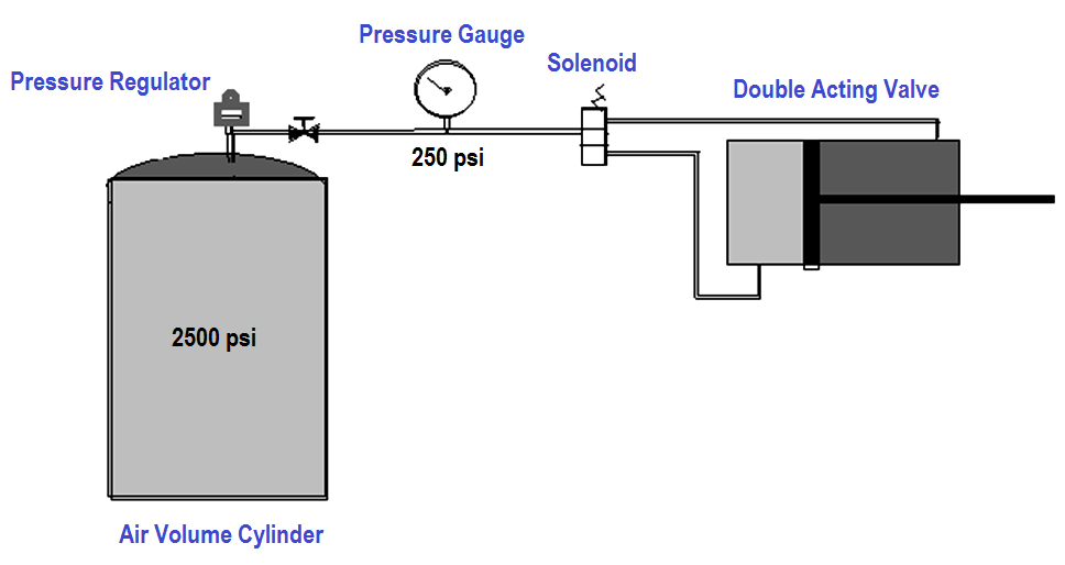
A 88 cubic inch HPA tank with a 2500 psi tank pressure, 250 psi regulated pressure, and a double-acting cylinder with a 4″ bore and a 6″ throw with a 1″ rod to actuate a mechanical device.

Let us find out how much-compressed air is in the tank.

P1 x V1 = P2 x V2

2500 x 88 = 250 x V2

220000   = 250 x V2

220000 / 250 = V2

V2 = 880 cubic inches, at 250 psi

Example 2:

Using the example above, find out how much volume is in the cylinder using the formula

Volume = Area (bore) x Length (throw).

The Push Stroke V = ((1/2 bore)^2 x Pi) x throw

 V = ((1/2 4)^2 x Pi) x 6

V = (2^2 x Pi) x 6

V = 12.56 x 6 V

 = 75.36 cubic inches

The Pull Stroke Vrod = ((.5)^2 x Pi) x 6 Vrod = 4.71 cubic inches

 V = 75.36 (The Push Stroke V) – 4.71(The Pull Stroke Vrod) = 70.65 cubic inches

The total volume for the push, stroke (75.36), pull stroke (70.65)

If we add them together to get 146.01 cubic inches.

If we divide that number into the available volume that the tank has: Force = Area x Pressure

and we know that we have an area = 12.56 square inches on the face of the piston in the ‘push’ stroke

The area is equal to  (12.56 – 0.785) = 11.775 square inches on the face of the piston in the ‘pull stroke.

The Push Force = 12.56 x 250.

The Pull Force = 11.775 x 250

Reference

Read Next:

  • Control Valve Sizing
  • Types of Valve Actuators
  • Relation between Cv and Kv
  • Types of Failures in Valves
  • Control Valve Stroke Test

Don't Miss Our Updates
Be the first to get exclusive content straight to your email.
We promise not to spam you. You can unsubscribe at any time.
Invalid email address
You've successfully subscribed !

Continue Reading

What is a 3-way Solenoid Valve ?
Control Valve Interview Questions and Answers
Pressure to Current (P/I) Converter Principle
List of Valve Standards
System Architecture and Process Control Systems Philosophy
Control Valve Selection Tips
Share This Article
Facebook Whatsapp Whatsapp LinkedIn Copy Link
Share
1 Comment
  • ROHITH KUMAR SAINI says:
    May 17, 2020 at 1:28 pm

    I understand that the air consumption for a single pull and a single push stroke is calculated. Adding them we get consumption a single cycle. This article is very helpful for design Engineers.

    Reply

Leave a Reply Cancel reply

Your email address will not be published. Required fields are marked *

Stay Connected

128.3kFollowersLike
69.1kFollowersFollow
210kSubscribersSubscribe
38kFollowersFollow

Categories

Explore More

Pilot-operated Relief Valve Principle
Control Valve Installation, Maintenance, Disassembly & Reassembly
Metal Seated Valves and Soft Seated Valves : Differences
Instrumentation and Control (I&C) Design
Field Instruments Selection Aid
Comparison of Gate Valves and Globe Valves
What is a Pilot Valve? When do we use a Pilot Valve?
Pressure Gauge Maintenance and Troubleshooting

Keep Learning

Design Engineering of Process Plant Project

Process Engineering Roles & Responsibilities – Design Company

ON OFF Valve Parts

ON OFF Valve Preventive Maintenance and Testing Procedure

Guided Wave Radar Level Transmitter Compensation

Guided Wave Radar Level Sensor Pressure and Temperature Effects

Instrument Process Datasheet

Instrument Process Datasheet (IPDS)

Transmitter Performance and Calibration Frequency

How to Calculate Transmitter Performance and Calibration Frequency?

What is Directional Control Valve (DCV)?

What is Directional Control Valve (DCV)?

Level Transmitter Design

Level Transmitter and Level Gauge Design Tips

Pinch Valve

What is Pinch Valve ?

Learn More

Calculate Power in Series RC Circuit

Calculate Power in Series RC Circuit

Power Electronics Objective Questions

Choppers Quiz

Control Systems Stability and Algebraic Criteria

Necessary Conditions for Stability & Non-Linear Systems

Multiphase Flow Meter Calibration Procedure

Multiphase Flow Meter Calibration Procedure

Top 100 LabVIEW Projects for Engineering Students

Top 100 LabVIEW Projects for Engineering Students

neutral-grounding-practice-in-power-system

Neutral Grounding Practice in Power System

Ion Spectrometers Questions & Answers

Instrumentation of Ion Spectroscopy

Control Valve Testing for Noise Measurement

Control Valve Testing for Noise Measurement

Menu

  • About
  • Privacy Policy
  • Copyright

Quick Links

  • Learn PLC
  • Helping Hand
  • Part Time Job

YouTube Subscribe

Follow US
All rights reserved. Reproduction in whole or in part without written permission is prohibited.
Welcome Back!

Sign in to your account

Username or Email Address
Password

Lost your password?