Inst ToolsInst ToolsInst Tools
  • Courses
  • Automation
    • PLC
    • Control System
    • Safety System
    • Communication
    • Fire & Gas System
  • Instrumentation
    • Design
    • Pressure
    • Temperature
    • Flow
    • Level
    • Vibration
    • Analyzer
    • Control Valve
    • Switch
    • Calibration
    • Erection & Commissioning
  • Interview
    • Instrumentation
    • Electrical
    • Electronics
    • Practical
  • Q&A
    • Instrumentation
    • Control System
    • Electrical
    • Electronics
    • Analog Electronics
    • Digital Electronics
    • Power Electronics
    • Microprocessor
  • Request
Search
  • Books
  • Software
  • Projects
  • Process
  • Tools
  • Basics
  • Formula
  • Power Plant
  • Root Cause Analysis
  • Electrical Basics
  • Animation
  • Standards
  • 4-20 mA Course
  • Siemens PLC Course
Reading: Electro Pneumatic Valve Positioner Schematic & Principle
Share
Font ResizerAa
Inst ToolsInst Tools
Font ResizerAa
  • Courses
  • Design
  • PLC
  • Interview
  • Control System
Search
  • Courses
  • Automation
    • PLC
    • Control System
    • Safety System
    • Communication
    • Fire & Gas System
  • Instrumentation
    • Design
    • Pressure
    • Temperature
    • Flow
    • Level
    • Vibration
    • Analyzer
    • Control Valve
    • Switch
    • Calibration
    • Erection & Commissioning
  • Interview
    • Instrumentation
    • Electrical
    • Electronics
    • Practical
  • Q&A
    • Instrumentation
    • Control System
    • Electrical
    • Electronics
    • Analog Electronics
    • Digital Electronics
    • Power Electronics
    • Microprocessor
  • Request
Follow US
All rights reserved. Reproduction in whole or in part without written permission is prohibited.
Inst Tools > Blog > Control Valves > Electro Pneumatic Valve Positioner Schematic & Principle

Electro Pneumatic Valve Positioner Schematic & Principle

Last updated: March 21, 2019 3:20 pm
Editorial Staff
Control Valves
1 Comment
Share
2 Min Read
SHARE

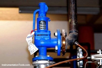
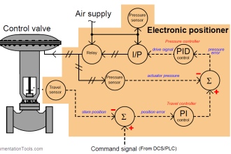
Electro Pneumatic valve Positioner is used to control the valve stem position from open to close position or vice versa.

A simple design and concept equals a simple operation of these components:

  • A pneumatic positioner
  • A manifold coupled I/P converter

Electropneumatic valve Positioner

Electropneumatic Valve Positioner Working Principle

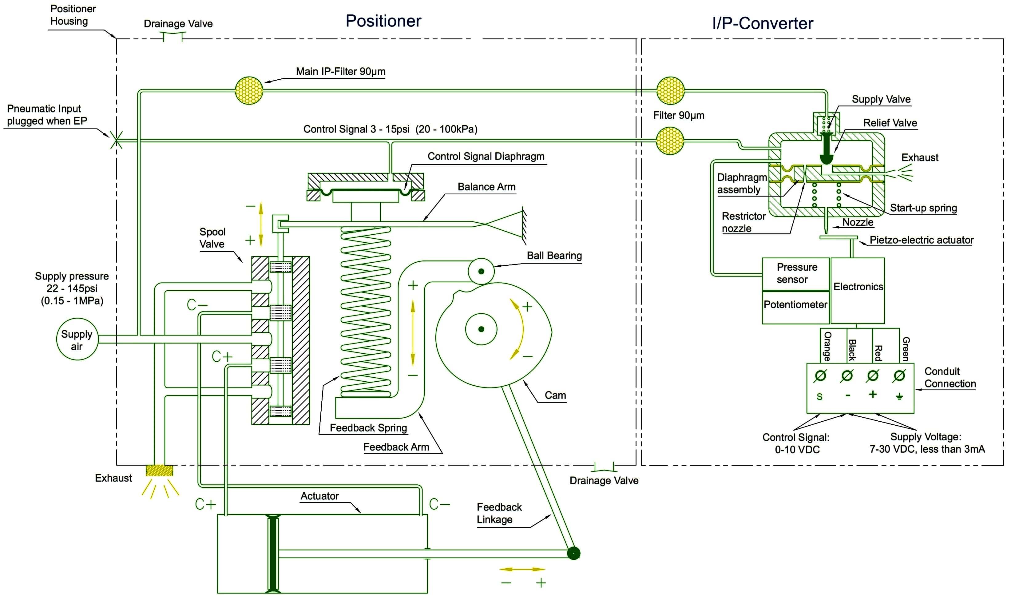
Image Courtesy : Valve Accessories

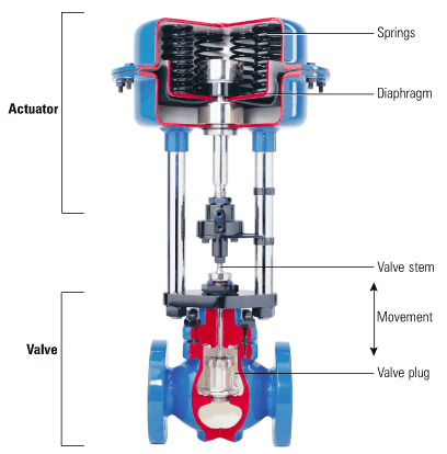
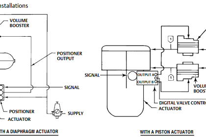
Supply pressure up to 145 PSI is connected to the supply port of the unit (marked S on the gauge block side), and the actuator ports (marked C+ and C-) are connected to either a double or single acting (spring return actuator-rotary or linear) actuator.

The C+ port is the positioners opening port.

An instrument signal (generally 4-20 mA) is then connected to the I/P connection block. The pneumatic Ip port (located on the ¼” porting side) should be plugged.

With no electronic signal on the unit, the positioner is stable, but no actuator movement has occurred.

The I/P is directly coupled with the pneumatic positioner; either internally mounted our externally mounted (EX and FF units) with a custom designed adapter.

Air supply for the I/P (up to 145 psi) is provided through the positioners supply port. The I/P converter will convert the 0-10V DC signal to a 3-15 psi signal sent internally to the positioner diaphragm.

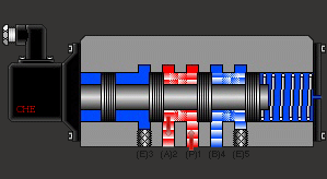
A voltage change causes the I/P to respond and sends a pneumatic signal (internally) to the positioner diaphragm, causing the diaphragm to move and the spool valve (air shuttle valve) to move, sending air to the actuator.

As the actuator moves, feedback to the positioner is provided through the actuator linkage and the positioner spindle/cam assembly.

As the actuator moves the spindle/cam rotates and turns to the desired “set point” based on the mA input signal. Once the set point is achieved a steady state position is maintained, and the supply air is “balanced” between ports.

Also Read : 
Electronic Valve Positioner
Basics of Valve Positioners
Functional Testing of Valve Positioners
Pneumatic Valve Positioner
Smart Valve Positioner
Don't Miss Our Updates
Be the first to get exclusive content straight to your email.
We promise not to spam you. You can unsubscribe at any time.
Invalid email address
You've successfully subscribed !

Continue Reading

Globe Valve Seat and Disk
Emergency Shutdown Valve : Advantages
Pneumatic Piping Design and Specification
Electric Motor Actuator Parts
Types of Valve Leakage Tests
What is a Fail-Close Valve? – Advantages and Disadvantages
Share This Article
Facebook Whatsapp Whatsapp LinkedIn Copy Link
Share
1 Comment
  • R S Raghavan says:
    July 11, 2018 at 11:17 am

    In general almost all your articles are impressive. As a past practitioner and present trainer of process Instrumentation I have gained by seeing some of the articles on instrument tools. There are a few areas specifically in process analytics and signal communication I may have something to offer.
    Nice to know that you are also BITS Pilani alumni like me. I passed out ME Electron Microwave Devices in 1972

    Reply

Leave a Reply Cancel reply

Your email address will not be published. Required fields are marked *

Stay Connected

128.3kFollowersLike
69.1kFollowersFollow
210kSubscribersSubscribe
38kFollowersFollow

Categories

Explore More

Constant Flow Valve Principle
Globe Valve Body Design
What is a 2-way Solenoid Valve ?
Spring and Diaphragm Pneumatic Actuators
What is a Servo Valve? – Principle and Advantages
Pilot-operated Relief Valve Principle
How to Install a Control Valve?
How Needle Valve Works ?

Keep Learning

Triple-offset Butterfly Valves

Butterfly Valves – Concentric, Double-offset, and Triple-offset

On Off Valve Root Cause Analysis

Root Cause Analysis for FRP Line Damaged due to On-Off Valve

How to Troubleshoot Control Valve - Problems and Solutions

How to Troubleshoot Control Valve? – Problems and Solutions

Diaphragm valves

Basics of Valves

3-way solenoid valves control instrument air pressure

Solenoid Valve’s Energized or De-energized State ?

ball Valve Animation

Basics of Ball Valves

What is Partial Stroke Test

What is Partial Stroke Test?

Control Valve flow coefficient (Cv)

Why we Measure Control Valve flow coefficient (Cv)?

Learn More

Liquid Level Control using Flow Loop

Liquid Level Control using Flow Loop

Encoder Principle

Encoder Working Principle

PLC Training Data Tables FIFO and LIFO

FIFO Instruction in Allen Bradley PLC Programming

Delta PLC Simulator

How to Work with Delta PLC Simulator?

Power Electronics Objective Questions

SCR Commutation Objective Questions

Falling Ball Viscometer Principle

Falling Ball Viscometer Principle

Laminar Flow Meter Working Principle

Laminar Flow Meter Working Principle

Circuit Measurement Objective Questions

Electrical and Electronics Circuit Measurement Objective Questions

Menu

  • About
  • Privacy Policy
  • Copyright

Quick Links

  • Learn PLC
  • Helping Hand
  • Part Time Job

YouTube Subscribe

Follow US
All rights reserved. Reproduction in whole or in part without written permission is prohibited.
Welcome Back!

Sign in to your account

Username or Email Address
Password

Lost your password?