Inst ToolsInst ToolsInst Tools
  • Ask
  • Courses
  • Videos
  • Q & A
    • Interview
      • Instrumentation
      • Electronics
      • Electrical
      • Practical Questions
    • MCQ
      • Instrumentation MCQ
      • Electrical MCQ
      • Electronics MCQ
      • Control Systems MCQ
      • Analog Electronics MCQ
      • Digital Electronics MCQ
      • Power Electronics MCQ
      • Microprocessor MCQ
      • Multiple Choice Questions
  • EE
    • Electronics
      • Electronics Q & A
      • Electronic Basics
      • Electronic Devices & Circuits
      • Electronics Animation
      • Digital Electronics
    • Electrical
      • Electrical Basics
      • Electrical Q & A
      • Power Electronics
      • Electrical Machines
      • Electrical Animation
      • Power Systems
      • Switchgear & Protection
      • Transmission & Distribution
  • Measure
    • Control Valves
    • Calibration
    • Temperature
    • Pressure
    • Flow
    • Level
    • Analyzers
    • Switches
    • Vibration
    • Solenoid Valve
  • Control
    • PLC Tutorials
    • Control Systems
    • Safety Instrumented System (SIS)
    • Communication
    • Fire & Gas System
  • More
    • Design
    • Tools
    • Animation
    • Basics
    • Formulas
    • Standards
    • TextBooks
    • Common
    • Software
    • Excel Tools
    • Erection & Commissioning
    • Process Fundamentals
    • Videos
    • Books
Search
All rights reserved. Reproduction in whole or in part without written permission is prohibited.
Reading: Electronic Force Balance Pressure Transmitter
Share
Notification Show More
Font ResizerAa
Inst ToolsInst Tools
Font ResizerAa
  • Courses
  • PLC Tutorials
  • Control Systems
Search
  • Ask
  • Courses
  • Videos
  • Q & A
    • Interview
    • MCQ
  • EE
    • Electronics
    • Electrical
  • Measure
    • Control Valves
    • Calibration
    • Temperature
    • Pressure
    • Flow
    • Level
    • Analyzers
    • Switches
    • Vibration
    • Solenoid Valve
  • Control
    • PLC Tutorials
    • Control Systems
    • Safety Instrumented System (SIS)
    • Communication
    • Fire & Gas System
  • More
    • Design
    • Tools
    • Animation
    • Basics
    • Formulas
    • Standards
    • TextBooks
    • Common
    • Software
    • Excel Tools
    • Erection & Commissioning
    • Process Fundamentals
    • Videos
    • Books
Follow US
All rights reserved. Reproduction in whole or in part without written permission is prohibited.
Inst Tools > Blog > Practical Questions > Electronic Force Balance Pressure Transmitter

Electronic Force Balance Pressure Transmitter

Understand how an electronic force-balance pressure transmitter uses a hall effect sensor to measure the pressure.

Last updated: October 27, 2020 12:46 pm
Editorial Staff
Practical Questions
No Comments
Share
2 Min Read
SHARE

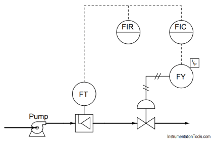
Shown here is a diagram for an electronic force-balance pressure transmitter:

Contents
Force Balance Pressure TransmitterHall Effect

Force Balance Pressure Transmitter

Electronic Force Balance Pressure Transmitter

Explain the following things in reference to this transmitter:

  1. What is a flexure?
  2. How is the opposing force generated?
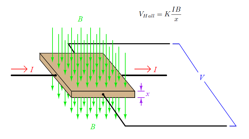
  3. What does a Hall Effect sensor do?
  4. How is an imbalance of force detected?
  5. How would you incorporate a zero adjustment into this transmitter?
  6. How would you incorporate a span adjustment into this transmitter?

A flexure is a thin strip of springy material, usually spring steel, designed to act as a frictionless fulcrum and/or a pivoting link. Unlike bearings, flexures are usually not able to handle a lot of angular motion. Hall Effect sensors are used to detect magnetic fields.

They generate a DC voltage proportional to the magnitude and polarity of an applied magnetic field and the magnitude and direction of a perpendicular DC current:

Hall Effect

What does a Hall Effect sensor do

The operation of the Hall Effect sensor may not be clear to all readers. It is oriented such that the magnetic field is parallel to the Hall Voltage axis and not perpendicular to it, when the beam is exactly level.

When the beam tips up or down, however, the magnetic flux lines passing from the “North” tip of the beam’s magnet to the “South” tip of the stationary magnet to the left of the Hall Effect sensor will angle, passing through the Hall Effect sensor with a definite direction, either up or down, depending on which way the beam tips:

Hall Effect Sensor Working and Applications

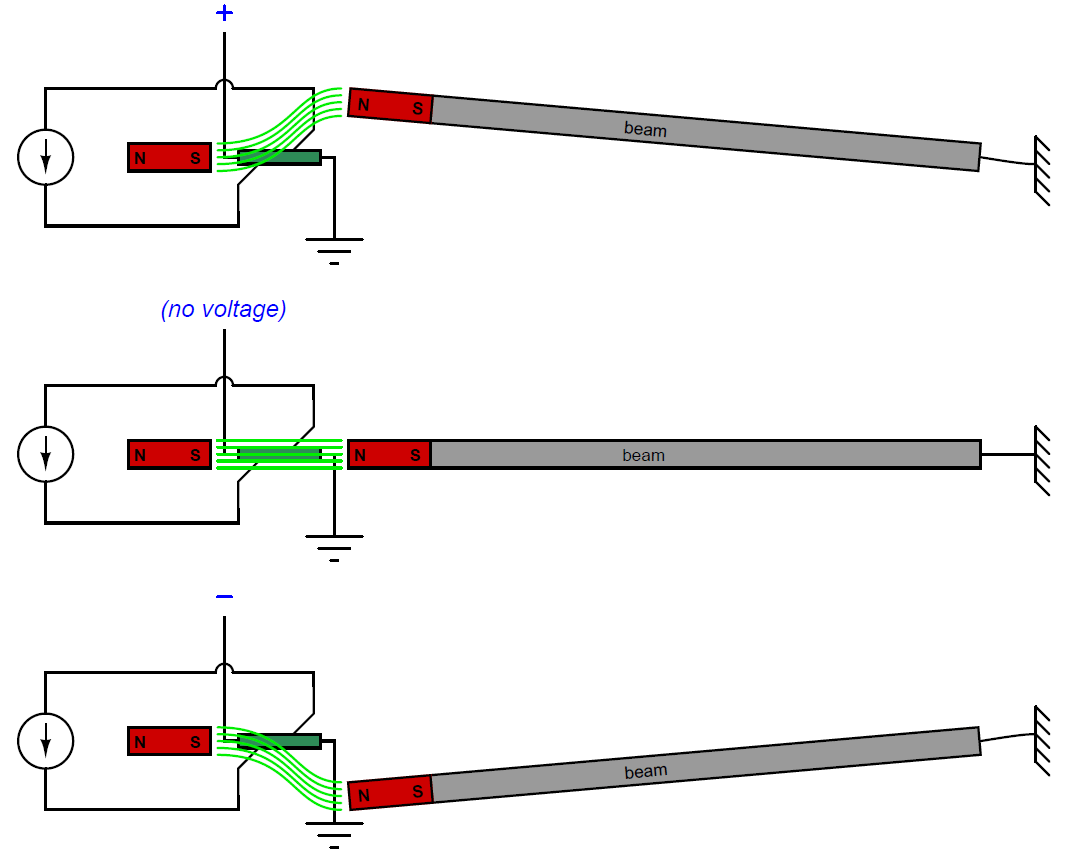
Thus, any output voltage from the Hall Effect sensor indicates an out-of-balance condition between the diaphragm and force motor.

The applied pressure changes the position of the beam, thus the hall effect sensor voltage varies in accordance with the measured pressure and by using this we can measure the applied pressure.

Note: These are very old models and obsolete now.

Read Next:

  • PT Re-Range Question
  • DP Pneumatic Transmitter
  • DP Transmitter Problem
  • Pressure Gauge Errors
  • Pneumatic Force Balance

Credits: Tony R. Kuphaldt

Don't Miss Our Updates
Be the first to get exclusive content straight to your email.
We promise not to spam you. You can unsubscribe at any time.
Invalid email address
You've successfully subscribed !
Calculate PSV Lift Pressure
Programmable Logic Controller (PLC) Questions and Answers – 8
Determine the Pressure at Each Port of DP Transmitter
Calculate Hydraulic System Fluid Pressure
Pressure Gauge with Block and Bleed Valves
Share This Article
Facebook Whatsapp Whatsapp LinkedIn Copy Link
Share
Leave a Comment

Leave a Reply Cancel reply

Your email address will not be published. Required fields are marked *

Stay Connected

128.3kFollowersLike
69.1kFollowersFollow
208kSubscribersSubscribe
38kFollowersFollow

Categories

Recent Comments

  • Kamli on Top Free PLC Software
  • Guifty Shimica on Top Non-PLC Certification Courses for Automation Professionals
  • Guifty Shimica on Top Non-PLC Certification Courses for Automation Professionals
  • MIHARITSOA Aina Sitraka on Top Non-PLC Certification Courses for Automation Professionals

Related Articles

level control system

Practical Process Control System Questions & Answers – 11

Differential Pressure Measurement across Baghouse

Differential Pressure Measurement across Baghouse

Bourdon Tube Gauge Spiral Spring

What is the Purpose of Bourdon Tube Gauge Spiral Spring?

burner management system P&ID

Solenoid Valves Questions & Answers – 1

two chemical streams are mixed together

Practical Process Control System Questions & Answers – 8

Two pressure switches

Identify Two Pressure Switches Logic

Allen-Bradley MicroLogix controller

Programmable Logic Controller (PLC) Questions and Answers – 16

Diagnosing the Electric Motor Circuit

Diagnosing Electric Motor Circuit

More Articles

Globe Valve Parts

What is Globe Valve ?

Thermocouple Standard

Thermocouple Details

Role of Flow Meters in a Laboratory

Role of Flow Meters in a Laboratory

LRV and URV of PT for Extreme Limits of Empty and Full

LRV and URV of PT for Extreme Limits of Empty and Full

Comparison of Humidity Sensors - Industrial Instruments

Comparison of Humidity Sensors – Industrial Instruments

WinCC data logging

How to Export Data from WinCC Runtime Advanced into Excel using VB Script

Electrical Machines Questions and Answers

Measurement of Xd and Xq – Synchronous Machine

Single Phase Motor Manual Controller

Motor Controllers

Follow US
All rights reserved. Reproduction in whole or in part without written permission is prohibited.
Welcome Back!

Sign in to your account

Username or Email Address
Password

Lost your password?