Inst ToolsInst ToolsInst Tools
  • Courses
  • Automation
    • PLC
    • Control System
    • Safety System
    • Communication
    • Fire & Gas System
  • Instrumentation
    • Design
    • Pressure
    • Temperature
    • Flow
    • Level
    • Vibration
    • Analyzer
    • Control Valve
    • Switch
    • Calibration
    • Erection & Commissioning
  • Interview
    • Instrumentation
    • Electrical
    • Electronics
    • Practical
  • Q&A
    • Instrumentation
    • Control System
    • Electrical
    • Electronics
    • Analog Electronics
    • Digital Electronics
    • Power Electronics
    • Microprocessor
  • Request
Search
  • Books
  • Software
  • Projects
  • Process
  • Tools
  • Basics
  • Formula
  • Power Plant
  • Root Cause Analysis
  • Electrical Basics
  • Animation
  • Standards
  • 4-20 mA Course
  • Siemens PLC Course
Reading: What is an Electrical Wire Mesh?
Share
Font ResizerAa
Inst ToolsInst Tools
Font ResizerAa
  • Courses
  • Design
  • PLC
  • Interview
  • Control System
Search
  • Courses
  • Automation
    • PLC
    • Control System
    • Safety System
    • Communication
    • Fire & Gas System
  • Instrumentation
    • Design
    • Pressure
    • Temperature
    • Flow
    • Level
    • Vibration
    • Analyzer
    • Control Valve
    • Switch
    • Calibration
    • Erection & Commissioning
  • Interview
    • Instrumentation
    • Electrical
    • Electronics
    • Practical
  • Q&A
    • Instrumentation
    • Control System
    • Electrical
    • Electronics
    • Analog Electronics
    • Digital Electronics
    • Power Electronics
    • Microprocessor
  • Request
Follow US
All rights reserved. Reproduction in whole or in part without written permission is prohibited.
Inst Tools > Blog > Electronic Basics > What is an Electrical Wire Mesh?

What is an Electrical Wire Mesh?

Last updated: October 30, 2019 11:04 am
Editorial Staff
Electronic Basics
No Comments
Share
4 Min Read
SHARE

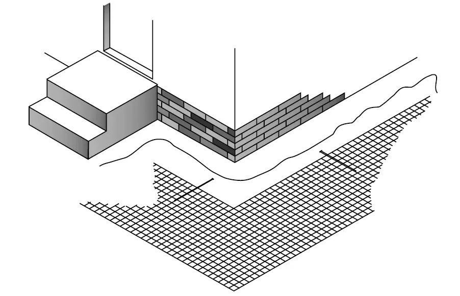
Electrical wire mesh is a convenient, efficient and economical means of improving grounding systems at large industrial facilities of high voltage installations and wherever large area communications grounds are required.

Wire Mesh reduces step and touch potentials at substations and effectively minimizes ground plane fluctuations at communications antenna sites. This mesh is also an excellent antenna ground plane, reflector and electronic shield for large facilities.

Electrical Wire Mesh

Electrical Wire Mesh

Personnel Safety Mats of prefabricated wire mesh are ideal safety mats to protect operators against lethal touch potentials at manually operated disconnect switches.

Prefabricated wire mesh is made from solid wire, either copper or copperbonded steel wire. The copperbonded wire has the strength of steel and the conductivity and corrosion resistance of copper. It is available in either 30% or 40% conductivity of copper, although 30% is the most popular.

All joints of the prefabricated wire mesh are silver brazed at the wire crossing points. This method provides joints strong enough to resist separation during installation and to bear the traffic of construction vehicles. Like the wire itself, the silver brazed joints are highly resistant to corrosion.

A non- corrosive flux is used in the brazing process that will not promote corrosion after the mesh is installed. The electrical conductivity of a silver brazed joint is excellent because of the low resistivity of the silver brazing material.

Prefabricated wire mesh is custom made to meet the needs of the installation. Wire size can range from No.6 AWG to No.12 AWG (0.162 inch to 0.081 inch diameter). Widths up to 20 feet (6.0 m) are available. The length will depend on the roll weight which has a limit of 500 pounds (227 kg).

Prefabricated mesh is easily installed with no digging or trenching. It is simply unrolled like a roll of carpeting.

Communications and shielding applications require connections to the grounding electrode system. When used as shielding inside a building, it is attached to the floor, walls and/or ceiling, depending upon the installation. It can be stapled to the wall studs or ceiling joists before the finished surface is installed.

Mesh can also be installed in the concrete slab to be used as a signal reference grid (SRG). Embedded ground plates connected to the mesh and flush with the floor are used to connect to the equipment. While thin flat strip SRGs are usually used and laid on top of the finished concrete, embedded mesh installations are also popular.

Prefabricated wire mesh, when installed in large areas requiring interconnections between rolls, is furnished with the cross wires overhanging the outside long wire equal to an amount of 1/2 the mesh size plus 2 inches.

When prefabricated wire mesh is used for personnel protection from faults at switch handles, it is usually made in 4 by 4 feet or 4 by 6 feet rectangular sheets although larger sizes can be made. Some users also purchase the mesh in rolls and cut off pieces as needed.

Do you face any problems with grounding? Share with us.

Reference: erico

Read Next:

  • Where to Terminate the Cable Shield?
  • Advantages of Grounding
  • Questions on Hazardous Area Safety
  • Different Types of Maintenance
  • Study about Electrical Standards
Don't Miss Our Updates
Be the first to get exclusive content straight to your email.
We promise not to spam you. You can unsubscribe at any time.
Invalid email address
You've successfully subscribed !

Continue Reading

Factors Affecting Inductance
Difference between Intrinsic and Extrinsic Semiconductors
Power Supply Circuit Fault Analysis
How to Test a Transistor ?
Difference Between Electrical and Electronic Devices
Electrical Static Grounding Techniques
Share This Article
Facebook Whatsapp Whatsapp LinkedIn Copy Link
Share
Leave a Comment

Leave a Reply Cancel reply

Your email address will not be published. Required fields are marked *

Stay Connected

128.3kFollowersLike
69.1kFollowersFollow
210kSubscribersSubscribe
38kFollowersFollow

Categories

Explore More

How to Measure capacitance using Multimeter
How to Measure AC Voltage using Multimeter
How to Identify the Transistor Terminals
Clamp Meters Working Principle
What are Analog and Digital Signals? Differences, Examples
What is Cathode Ray oscilloscope ?
Difference Between Common Cathode and Common Anode 7 Segment LED Display?
What is a Clamp Meter?

Keep Learning

Measure Duty Cycle using Multimeter

How to Measure Duty Cycle using Multimeter

Accuracy, resolution, range, counts, digits and precision

Definition of Accuracy, Precision, Resolution, Range

Top Beginner Soldering Mistakes

Top Beginner Soldering Mistakes and How to Avoid Them?

Clamp Meter

Things to Know When Measuring Current

Top 100 555 Timer Projects for Engineering Students

Top 555 Timer Projects for Engineering Students

resistor-color-coding-example

IEC labelling for Resistors Color Code

Difference Between LED and LCD

Difference Between LED and LCD

Difference Between LED and LDR

Difference Between LED and LDR

Learn More

Shunt-Wound DC Generator Principle

Shunt-Wound DC Generators

Transformers Coolers Weld Joints Oil

Transformers Coolers Weld Joints Oil Oozes Were Eye Sores

Instrumentation Engineering Standards Interview Questions & Answers

Electrical Machines Objective Questions & Answers

Simple Loop with Local Indication

Instrument Loop Test Requirements and Operation Procedures

explosion-proof electrical enclosures

Classified Areas and Electrical Safety Measures

In-Situ Zirconia Oxygen Analyzer

Oxygen (O2) Measurement in Flue Gas

Power Electronics Objective Questions

Single Phase VSI Objective Questions

Disadvantages of Resistance Temperature Detectors (RTD)

Disadvantages of Resistance Temperature Detectors

Menu

  • About
  • Privacy Policy
  • Copyright

Quick Links

  • Learn PLC
  • Helping Hand
  • Part Time Job

YouTube Subscribe

Follow US
All rights reserved. Reproduction in whole or in part without written permission is prohibited.
Welcome Back!

Sign in to your account

Username or Email Address
Password

Lost your password?