Inst ToolsInst ToolsInst Tools
  • Courses
  • Automation
    • PLC
    • Control System
    • Safety System
    • Communication
    • Fire & Gas System
  • Instrumentation
    • Design
    • Pressure
    • Temperature
    • Flow
    • Level
    • Vibration
    • Analyzer
    • Control Valve
    • Switch
    • Calibration
    • Erection & Commissioning
  • Interview
    • Instrumentation
    • Electrical
    • Electronics
    • Practical
  • Q&A
    • Instrumentation
    • Control System
    • Electrical
    • Electronics
    • Analog Electronics
    • Digital Electronics
    • Power Electronics
    • Microprocessor
  • Request
Search
  • Books
  • Software
  • Projects
  • Process
  • Tools
  • Basics
  • Formula
  • Power Plant
  • Root Cause Analysis
  • Electrical Basics
  • Animation
  • Standards
  • 4-20 mA Course
  • Siemens PLC Course
Reading: Electrical Torsion Meter Principle
Share
Font ResizerAa
Inst ToolsInst Tools
Font ResizerAa
  • Courses
  • Design
  • PLC
  • Interview
  • Control System
Search
  • Courses
  • Automation
    • PLC
    • Control System
    • Safety System
    • Communication
    • Fire & Gas System
  • Instrumentation
    • Design
    • Pressure
    • Temperature
    • Flow
    • Level
    • Vibration
    • Analyzer
    • Control Valve
    • Switch
    • Calibration
    • Erection & Commissioning
  • Interview
    • Instrumentation
    • Electrical
    • Electronics
    • Practical
  • Q&A
    • Instrumentation
    • Control System
    • Electrical
    • Electronics
    • Analog Electronics
    • Digital Electronics
    • Power Electronics
    • Microprocessor
  • Request
Follow US
All rights reserved. Reproduction in whole or in part without written permission is prohibited.
Inst Tools > Blog > Common > Electrical Torsion Meter Principle

Electrical Torsion Meter Principle

Last updated: March 31, 2018 4:47 am
Editorial Staff
Common
No Comments
Share
2 Min Read
SHARE

Torque Measurement using slotted Discs

Due to the applied torque, there is a relative displacement between the two slotted discs. Due to this relative displacement of the slotted discs, a phase shift exists between the pulse generated by the transducers. When these pulses are connected to an electronic unit, it will show a time lapse between the two pulses. This time lapse between the two pulses is proportional to the twist of the shaft and the torque of the shaft.

Description of Electrical Torsion Meter

Electrical Torsion Meter

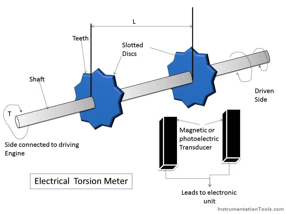
  1. The main parts of an electrical torsion meter are as follows:
  2. A shaft connected between a driving engine and a driven load.
  3. Two slotted discs attached on either side of the shaft.
  4. Transducer (magnetic or photo electric ) to count pulses from the slotted disc.

Operation of Electrical Torsion Meter

  1. The teeth produce voltage pulses in the transducers.
  2. When torque is not applied on the shaft, the teeth of the bth the discs perfectly align with each other and hence he voltage pulses produced in the transducers will have zero time difference.
  3. But when torque is applied on the shaft, there is a relative displacement of the slotted discs due to twist experienced by the shaft and hence the teeth of both the discs will not align with each other and hence the voltage pulses produced in the transducer will have a time difference (that is , time lapse).
  4. This time lapse between the pulses of the two discs is proportional to the twist of the shaft and hence the torque of the shaft.
  5. A measure of this time lapse becomes of torque when calibrated.

Application of Electrical Torsion Meter

  1. Used to measure torque on rotation shafts.

Advantages of Electrical Torsion Meter

  1. There are no signal leakage problems.
  2. There is no noise creation.
Don't Miss Our Updates
Be the first to get exclusive content straight to your email.
We promise not to spam you. You can unsubscribe at any time.
Invalid email address
You've successfully subscribed !

Continue Reading

Saybolt Viscometer
Top 3 Online Bachelor’s Programs in Electronics Engineering
How Not to Install an Instrument and Wrong Practices
How a Single ZTNA Solution Can Help Overcome Cybersecurity Issues?
Understanding the Chiller Maintenance – HVAC Tutorials
What is Transparent Solar Panel? – Working Principle and Theory
Share This Article
Facebook Whatsapp Whatsapp LinkedIn Copy Link
Share
Leave a Comment

Leave a Reply Cancel reply

Your email address will not be published. Required fields are marked *

Stay Connected

128.3kFollowersLike
69.1kFollowersFollow
210kSubscribersSubscribe
38kFollowersFollow

Categories

Explore More

Everything You Need to Know About Stainless Steel CNC Machined Parts
Steps Followed Before Creating CNC Program
Pilot Operated Back Pressure Regulator Valve Test
Types of Sensors Used in Automobiles
Deep Hole Drilling Ideal Methods For CNC Machining
Comparison of Humidity Sensors – Industrial Instruments
Difference between Anode and Cathode
5 Best Mobile Apps to Password Protect Applications and Files

Keep Learning

7 Marketing Strategies for Engineering Companies

7 Marketing Strategies for Engineering Companies

PM of Instrument Air Compressor

PM of Instrument Air Compressor in Oil & Gas Plants

FPGA vs. CPLD - What are the differences between them

FPGA vs. CPLD – What are the differences between them

Load Cell Assembly

Urea Bagging Plant – Process Flow

Career Opportunities and Scope in Industrial Automation

Career Opportunities and Scope in Industrial Automation

Difference Between Robotics and Automation

Difference Between Robotics and Automation

Advantages & Disadvantages of CNC Milling

What are the Advantages & Disadvantages of CNC Milling?

Why is Capacitor Used in a Fan

Why is Capacitor Used in a Fan?

Learn More

Electrical Machines Questions and Answers

Induction Motor Rotor Frequency

Center Tap Full-Wave Rectifier

Full-Wave Rectifier Circuit

Digital Control Systems

Compensation Techniques : Control Systems

Transistor as Amplifier

Transistor as Amplifier

Signal Strength of Guided-wave Radar Level Instrument

Signal Strength of Guided-wave Radar Level Instrument

Analytical Standards

Ball Valve Material Selection

Ball Valve Material Selection

How to Test a Thermocouple with a Multimeter

Testing a Thermocouple With a Multimeter

Menu

  • About
  • Privacy Policy
  • Copyright

Quick Links

  • Learn PLC
  • Helping Hand
  • Part Time Job

YouTube Subscribe

Follow US
All rights reserved. Reproduction in whole or in part without written permission is prohibited.
Welcome Back!

Sign in to your account

Username or Email Address
Password

Lost your password?