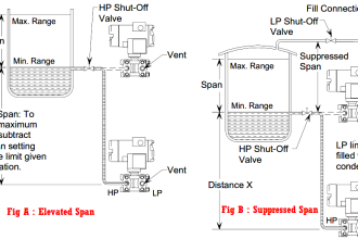
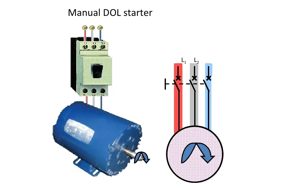
Manual DOL Starter :
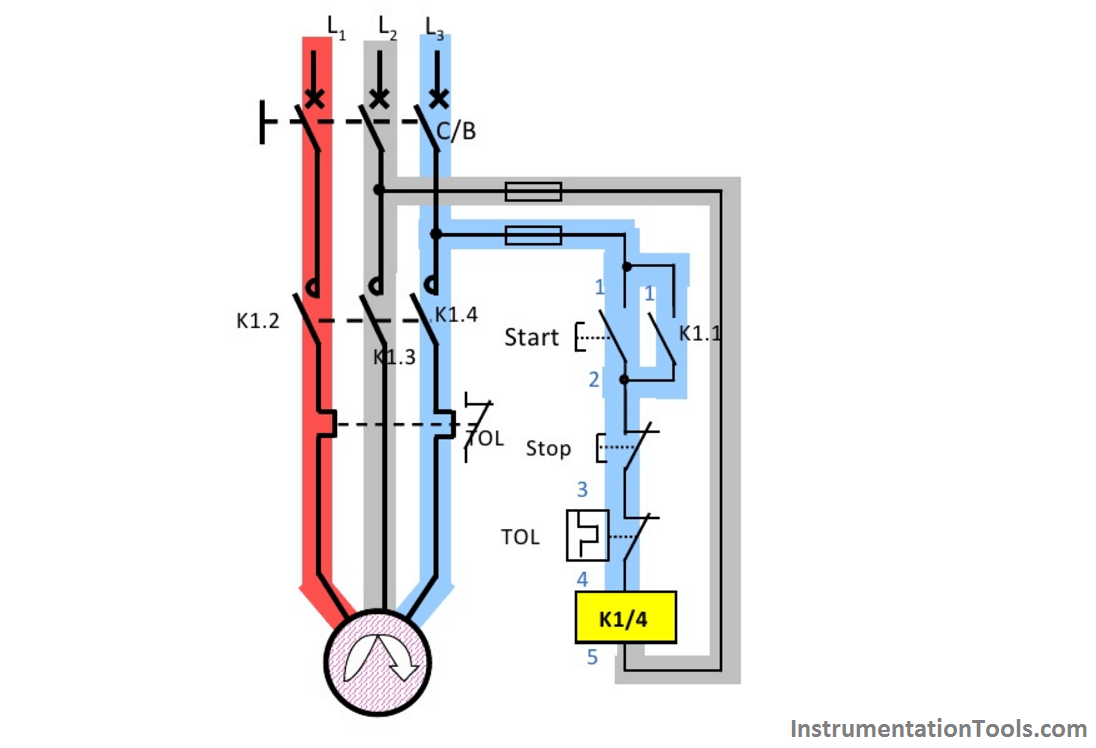
Contactor Controlled DOL Starter :
Read : Simple DOl Starter using PLC
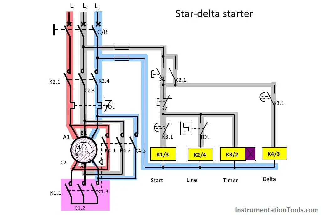
Motor Star Delta Starter :
Read : Star – Delta Starter Principle
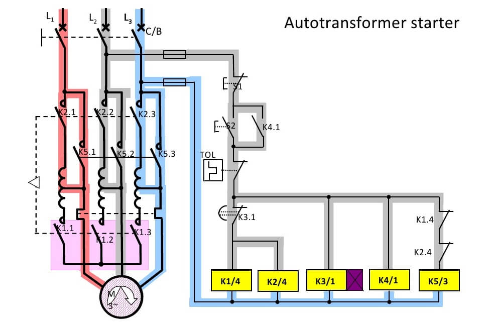
Motor Auto Transformer Starter
An Auto transformer Starter is suitable for both star and delta connected motors. In this method, the starting current is limited by using a three-phase auto transformer to reduce the initial stator applied voltage.
Instead of resistors, autotransformer starting uses a step down autotransformer (single-winding transformer) to reduce the line voltage. Autotransformer starters offer the greatest reduction of line current of any reduced-voltage starting method. Multiple taps on the transformer permit the voltage, current, and torque to be adjusted to satisfy many different starting conditions. In closed transition starting, the motor is never disconnected from the line source during acceleration.
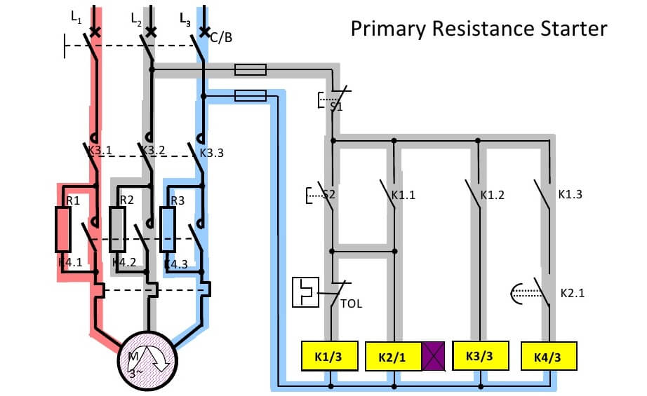
Motor Primary Resistance Starter
The motor is started by closing the main contactor. This supplies power to the motor through series starting resistance. The contactor (across resistors R1,R2,R3) is open thus the current has to pass through the resistors resulting in voltage drop. Due to voltage drop in these resistors, the motor gets reduced voltage. A timer is installed with a preset time delay. When the delay is over, the contactor is closed closing the parallel switches.
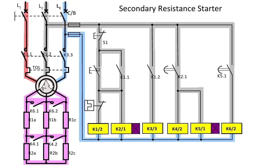
Motor Secondary Resistance Starter
The secondary resistance starter comprises a contactor to switch the stator and a series of resistors that are applied to the rotor circuit and gradually reduced in value as the motor accelerates to full speed. The rotor would normally be shorted out once the motor is at full speed. The resistor values are selected to provide the torque profile required and are sized to dissipate the slip power during start. The secondary resistors can be metallic resistors such as wound resistors, plate resistors or cast iron resistors.