Inst ToolsInst ToolsInst Tools
  • Courses
  • Automation
    • PLC
    • Control System
    • Safety System
    • Communication
    • Fire & Gas System
  • Instrumentation
    • Design
    • Pressure
    • Temperature
    • Flow
    • Level
    • Vibration
    • Analyzer
    • Control Valve
    • Switch
    • Calibration
    • Erection & Commissioning
  • Interview
    • Instrumentation
    • Electrical
    • Electronics
    • Practical
  • Q&A
    • Instrumentation
    • Control System
    • Electrical
    • Electronics
    • Analog Electronics
    • Digital Electronics
    • Power Electronics
    • Microprocessor
  • Request
Search
  • Books
  • Software
  • Projects
  • Process
  • Tools
  • Basics
  • Formula
  • Power Plant
  • Root Cause Analysis
  • Electrical Basics
  • Animation
  • Standards
  • 4-20 mA Course
  • Siemens PLC Course
Reading: Electrical Earthing Calculations
Share
Font ResizerAa
Inst ToolsInst Tools
Font ResizerAa
  • Courses
  • Design
  • PLC
  • Interview
  • Control System
Search
  • Courses
  • Automation
    • PLC
    • Control System
    • Safety System
    • Communication
    • Fire & Gas System
  • Instrumentation
    • Design
    • Pressure
    • Temperature
    • Flow
    • Level
    • Vibration
    • Analyzer
    • Control Valve
    • Switch
    • Calibration
    • Erection & Commissioning
  • Interview
    • Instrumentation
    • Electrical
    • Electronics
    • Practical
  • Q&A
    • Instrumentation
    • Control System
    • Electrical
    • Electronics
    • Analog Electronics
    • Digital Electronics
    • Power Electronics
    • Microprocessor
  • Request
Follow US
All rights reserved. Reproduction in whole or in part without written permission is prohibited.
Inst Tools > Blog > PLC Tutorials > Electrical Earthing Calculations

Electrical Earthing Calculations

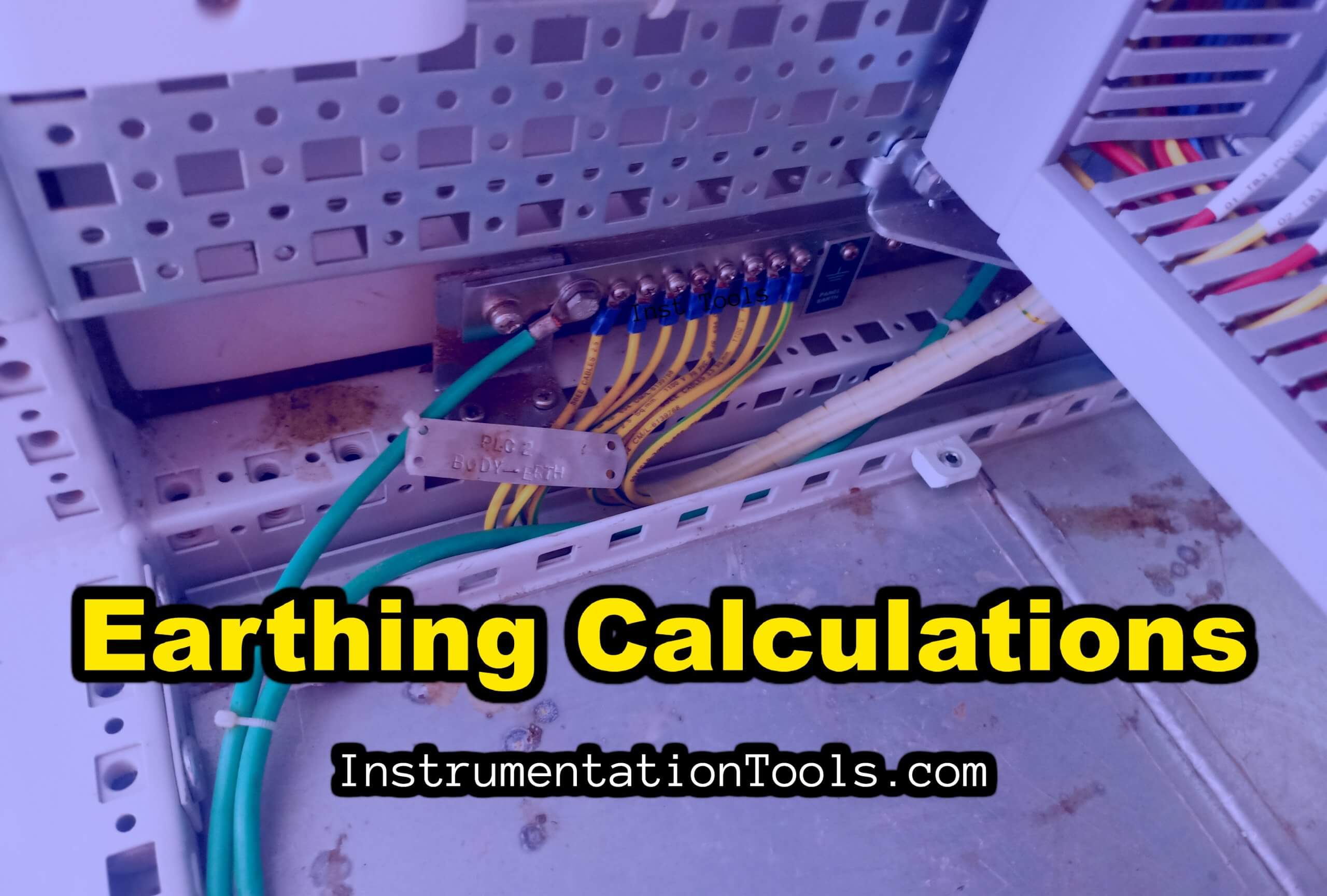
Learn the electrical earthing calculations to determine the number of earth pits and the size of the earth grid conductor.

Last updated: September 28, 2022 2:10 pm
Gaurav Lunagariya
PLC Tutorials Control Systems Electrical Basics
3 Comments
Share
5 Min Read
SHARE

In this article, we will discuss how to determine the number of earth pits, the size of the earth grid conductor, and the overall resistance of the earthing system.

Contents
Electrical Earthing CalculationsEarth Conductor SizingSurface Area of Solid Rod ElectrodeNumber of Earth ElectrodesResistance of Electrode

Electrical Earthing Calculations

Earthing Calculations

Sizing of earth grid conductor shall be done by considering fault current 1 sec. The uniform soil model assumption is based on a 3-meter long pipe electrode used at this installation which cannot penetrate to the second layer of lower soil resistivity.

The material of the earth grid conductor shall be galvanized iron (GI). GI strip shall be considered as the main earth conductor and earth electrodes shall be 80 mm dia pipe meeting the requirements of IS 3043.

The maximum value of a single line to earth fault current is considered as 80 kA. Based on soil resistivity testing at various locations, average soil resistivity 12.46 ohm-m shall be considered for earthing system calculation which is done by wenner’s method.

Electric Resistivity in ohm-m = 2πRS

Where,

 S: Distance between two electrodes in meter (m)

R: V/I: Resistance in Ohm Ω

Earth Conductor Sizing

The cross-sectional area of the earth conductor shall be such that the current density value determined by the following formula is not exceeded.

(I/S) = k (1/√ t)

Where;

I = Value of fault current which can flow through the protective device in amperes

S = Cross sectional area in sq.mm.

k = Factor dependent on the material of the protective conductor, the Insulation and other parts, and the initial and final temperatures.

t = Operating time of the disconnecting device in seconds

The factor k is determined from the formula:

k = sqrt [{Qc (B+20) / δ20)} x ln {1+ (θf – θ1) / (B + θ1)}]

Qc = Volumetric heat capacity of conductor material (J/ ºC mm3)

B = Reciprocal of temperature coefficient of Resistivity at 0ºC for the conductor (0ºC)

δ20 = Electrical Resistivity of conductor material at 20ºC (Ω-mm)

θ1 = Initial temperature of conductor (ºC)

θf = Final temperature of conductor (ºC)

For steel conductor;

Qc = 3.8 x 10⁻³ (J/ ºC mm3)

B = 202 ºC

δ20 = 138 x 10-6 (Ω-mm)

θ1 = 40 ºC

θf  = 500 ºC

 Put all values as given in equation, so we get,

k = 80.68 ≈ 80

Now, let’s find the cross-sectional area of the earth strip

S  =  (I x √ t) / k

(80000 x 0.6 x√ 1) /80    [As a total 60% of fault current will flow through the Earth conductor and the remaining 40% will flow through the soil. This is as per BS 7354 ]

S = 600 mm2

Hence S = 600 X 1.15 = 690 sq.mm. (Considering 15 % corrosion margin)

Hence GI Bar of size 36 X 36 sq. mm. size is considered adequate for the main buried earth grid conductor for the plant area.

Surface Area of Solid Rod Electrode

Ae = (π x D x l) m2

Where,

D = Diameter of electrode (m)

l  = Length of electrode (m)

Ae = (π x 0.08 x 3.00) m2 (for 80 mm diameter electrode)   

Ae = 0.8294 m2

Number of Earth Electrodes

Number of earth electrodes required to dissipate the fault current of 80kA are 

Area of electrodes required to dissipate fault current / Area of each electrode

Number of earth electrodes = 48.49 /0.8294

Number of earth electrodes = 58.46 Nos. (≈  60 Nos.)

Resistance of Electrode

R = (1/2 πl) x [(ρ – ρc) (ln (8L / D) – 1) + ρc (ln (8L / d) – 1)]

Where,

ρ = Resistivity of soil in Ω-m

ρc = Resistivity of infill material in Ω-m

d = Diameter of Electrode in meters

D = Diameter of infill material in meters

L = Driven length of electrode in meters

R =  (1/ 2 π x 3) x [ (12.46 – 3) (ln (8×3/0.45)-1) + 3 (ln ((8×3/0.08)-1)]

R  =  0.59 Ω

If you liked this article, then please subscribe to our YouTube Channel for Instrumentation, Electrical, PLC, and SCADA video tutorials.

You can also follow us on Facebook and Twitter to receive daily updates.

Read Next:

  • DOL Starter Circuit Diagrams
  • Earth Leakage Circuit Breaker
  • Star Delta Starter Circuit Diagrams
  • Control Two Motors after Time Delay
  • Thermal Protection Relay for Motors
Don't Miss Our Updates
Be the first to get exclusive content straight to your email.
We promise not to spam you. You can unsubscribe at any time.
Invalid email address
You've successfully subscribed !

Continue Reading

PLC Programming for Multi-Color Sorting Conveyor System
Motor Inrush Current Measurements
Ziegler-Nichols Open-Loop Method
PLC FBD Example for Tank Liquid Heating Control by Steam Flow
Corona Discharge in Power Transmission Lines
Difference Between Microcontroller and PLC
Share This Article
Facebook Whatsapp Whatsapp LinkedIn Copy Link
Share
3 Comments
  • ENOCK Samwel says:
    June 18, 2022 at 10:58 pm

    Great

    Reply
  • Abdalhameed stohy says:
    September 22, 2022 at 3:26 pm

    To calculate no of rods u use area required to dissipate fault current by 48 though it is calculated by 600mm2,how

    Reply
    • ksn murthy says:
      December 8, 2023 at 11:50 am

      I WANT SEE THE REPLY

      Reply

Leave a Reply Cancel reply

Your email address will not be published. Required fields are marked *

Stay Connected

128.3kFollowersLike
69.1kFollowersFollow
210kSubscribersSubscribe
38kFollowersFollow

Categories

Explore More

Partial Discharge in Power Lines and its Detection through Sensors
Derivative Controller Principle
Functional Block Diagram PLC Example for Traffic Light System
Difference Between Flame Resistant and Flame Retardant Cables
What is a GSD File and Why it is required?
Ladder Logic Programming Examples
How to Analyze PID Controller Actions
Difference between Current Transformer and Potential Transformer

Keep Learning

Two Out of Three Logic

Alarm and Trip Systems

Electrical Feeder Automation in Smart Grid

Electrical Feeder Automation in Smart Grid

How to Program Sequential Outputs in PLC

Timer-Based Sequential PLC Program with One Button

Two out of Three Logic Analogy

Siemens S7 300 and STEP 7 PLC program using SIMATIC Software

Electrical Terminology

Electrical Terminology

Difference between Feedback, Feedforward, and Cascade Control

Difference between Feedback, Feedforward, and Cascade Control?

PID block from the PLC library

How to Configure PID Controller in Various Schneider PLCs?

Learn More

SIS Verification & Validation - Safety Instrumented System

SIS Verification & Validation – Safety Instrumented System

PLC Controls a Valve

PLC Controls a Valve Video

Power Electronics Objective Questions

Thyristor Firing Objective Questions

hand-crank megger photo

What is Megger Test?

Flow Measurement Questions and Answers

80+ Flow Measurement Interview Questions and Answers

Instrumentation Deliverables Generated from 3D Modeling

Instrumentation Deliverables Generated from 3D Modeling

Electrical Voltage and current Signals

Electrical Voltage and current Signals

S84 - IEC 61511 Standard for Safety Instrumented Systems

S84 / IEC 61511 Standard for Safety Instrumented Systems

Menu

  • About
  • Privacy Policy
  • Copyright

Quick Links

  • Learn PLC
  • Helping Hand
  • Part Time Job

YouTube Subscribe

Follow US
All rights reserved. Reproduction in whole or in part without written permission is prohibited.
Welcome Back!

Sign in to your account

Username or Email Address
Password

Lost your password?