Interlocking logic in electrical control is one of the safest and reliable controls in the industrial sector in the case of controlling two or three motors. This interlocking logic is used in the application where the application of one of the motors depends on the status of the other motor. This means that if one of the motors is in running condition means the other two motors will not run as the circuit logic was designed. These types of interlocking systems were commonly used in the industrial automation sector, where the operation needs to be safe and reliable.
Components
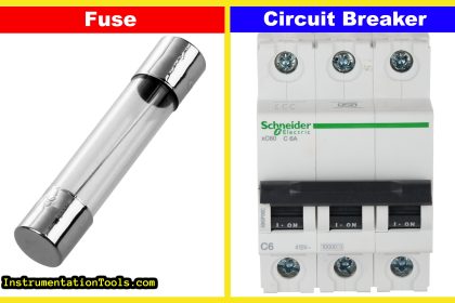
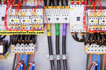
- Miniature Circuit Breaker
- Contactor
- Contactor Coil /Contacts
- Start & Stop Buttons
- Three Phase Power Supply
- Single Phase Power Supply
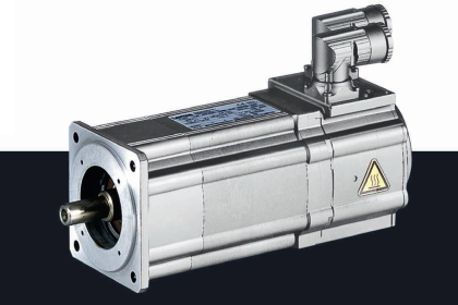
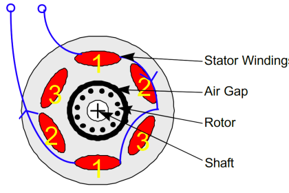
- Three Phase Induction Motor
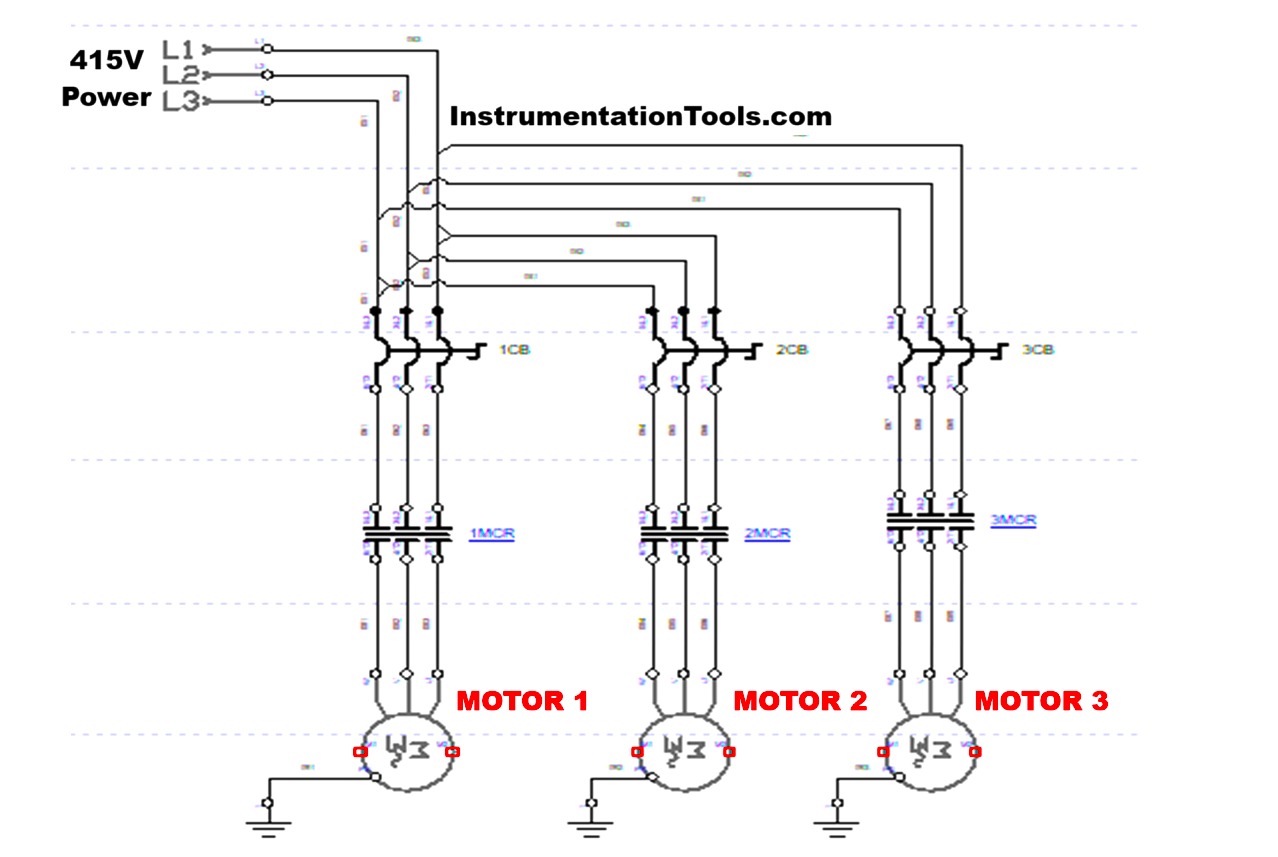
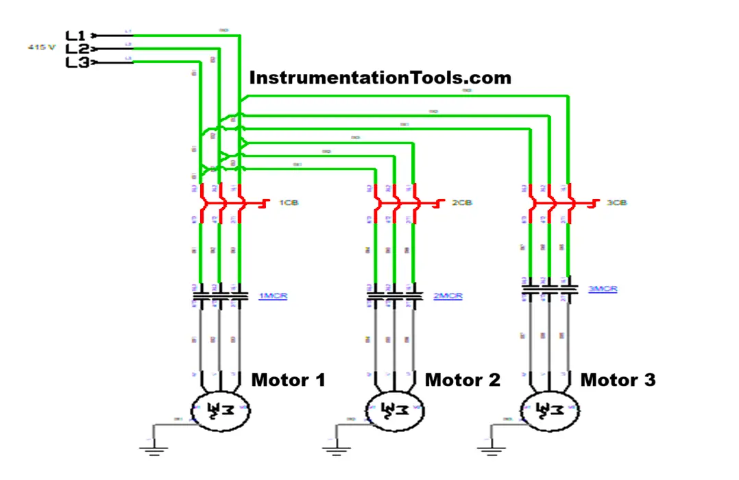
Power Circuit
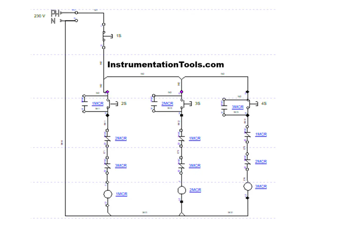
Control Circuit
Simulation Video
Circuit Operation Explained
- Three Phase supply was given to the system by connecting with the Miniature Circuit Breaker. Miniature Circuit Breaker prevents the overload or overvoltage to the system by its tripping mechanism.
- In our Project, we are using Three motors for interlocking purposes. All the motors were connected with the individual contactors and a Miniature Circuit Breaker. Because each one’s control should not disturb the other two.
- By turning on the three-phase supply, the power was given to the Miniature Circuit Breaker, and simultaneously single-phase supply was also turned on. Normally, Three phase supply was given to the power circuit where the load connection was there and Single-Phase supply was given to the control circuit where it controls the contactor coils.
- Single Phase supply was connected to the control button like Start (Normally Open) and Stop (Normally Close), and then it will supply to the contactor’s contacts and coils.
- For our project, we used three motors, and that three motors were controlled by three Push buttons, and the total circuit was controlled by a single stop button. Once this stop is pressed total circuit will be turned off.
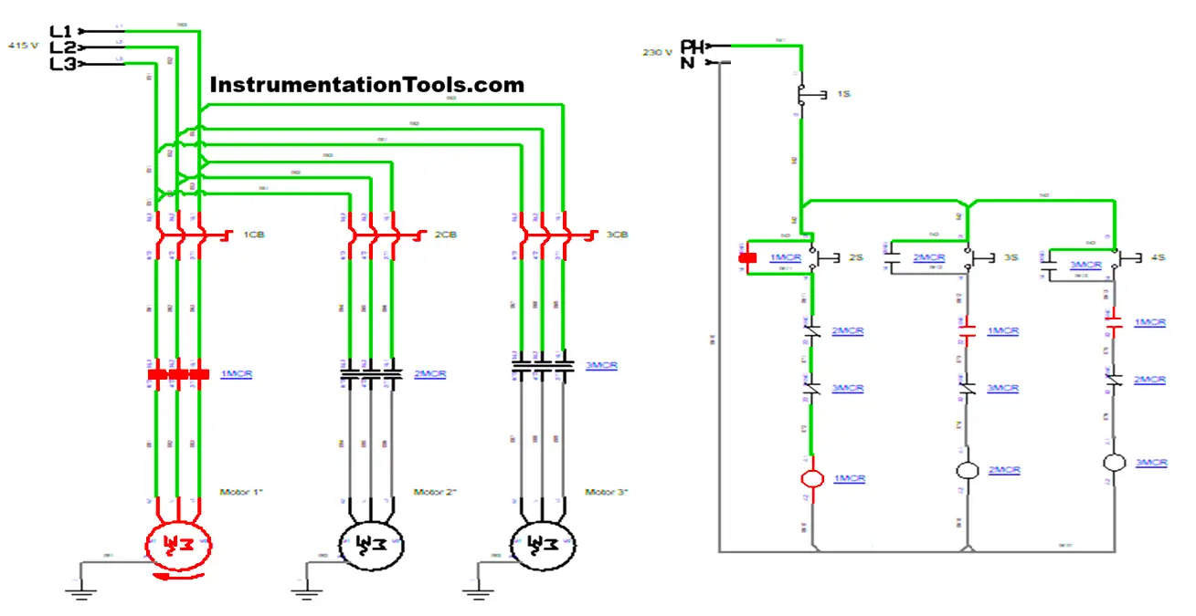
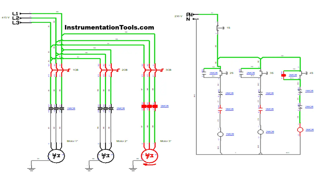
- Primarily, we are pressing the Start Button (2S), which makes the contactor 1 MCR energize and starts Motor 1 to rotate continuously. If we release the push button (2S), Motor 1 will rotate since it is a holding circuit. Similarly, the Normally close contact of 1 MCR is also executed, which cuts the supply of the other two contactor 2 MCR and 3 MCR. If we press the push buttons (3S) and (4S) also, the two contactor 2 MCR and 3 MCR will not get energized.
- If we want to operate Motor 2 or Motor 3, we want to shut off the circuit by pressing the Stop Button (1 S), and then we want to press the Push Buttons (3S) or (4S) as per the requirement.
- If we Press the 3S push button it will make contactor 2 MCR to energize and makes the Motor 2 rotate, on that time Motor 1 and Motor 3 will not rotate or if we press the 4 S push button means 3 MCR contactor will energize and Motor 3 will starts to rotate, om that time Motor 1 and Motor 2 will not rotate.
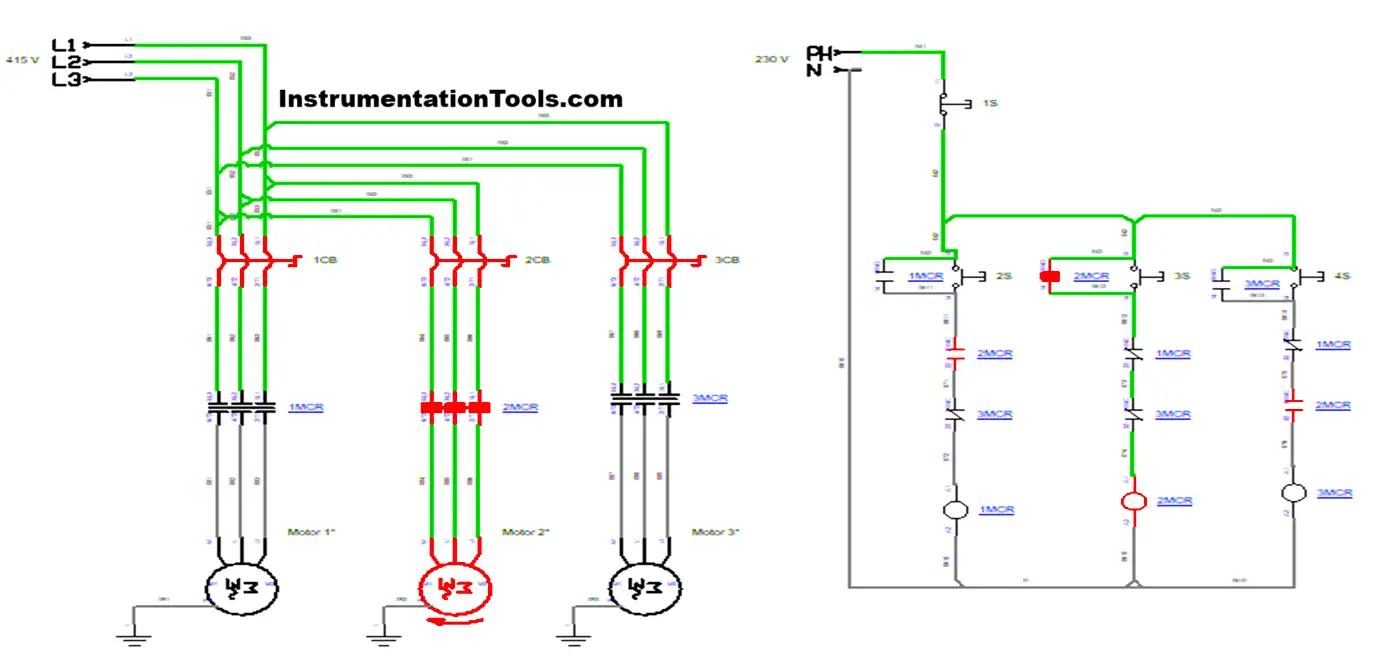
- Interlocking is nothing but, if we turn ON Motor 1, Motor 1 will start to rotate. At the same time, if we turn ON the other Motor 2 and Motor 3, they will not rotate. The Motor 1 normally close contact will be actuated, which will cut off the Motor 2 and Motor 3 supply.
- Simultaneously, if we first turn ON the Motor 2, the Motor 2 will start to rotate at the same time we turn ON the Motor 1 or Motor 3 means those motors will not rotate.
- If we need to start the next motor means we need to turn OFF the circuit by pressing the Stop button. Then the total circuit will be turned off.
- Then, we can turn ON any motor as per requirement, either Motor 1 or Motor 2, or Motor 3.
Conclusion
This interlocking control of three motors is one of the important, safe, and reliable operations in the industrial automation sector. By using this, we can safely operate all the motors, and by this equal amount of load is taken at the same time because at a time single motor is only operated, and this also avoids high inrush current, overheating, malfunctions, and unsafe operations. This will ensure the smooth workflow in the operations, and this control was mainly used in conveyor systems, process automation, manufacturing assembly lines, and water pumping systems.
Read Next:
- Phase Failure Relay in LV Panels
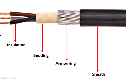
- How to Locate Faults in Cables?
- Variable Air Volume Controller
- Why is HV Testing important?
- Motor Control using Timer Circuit