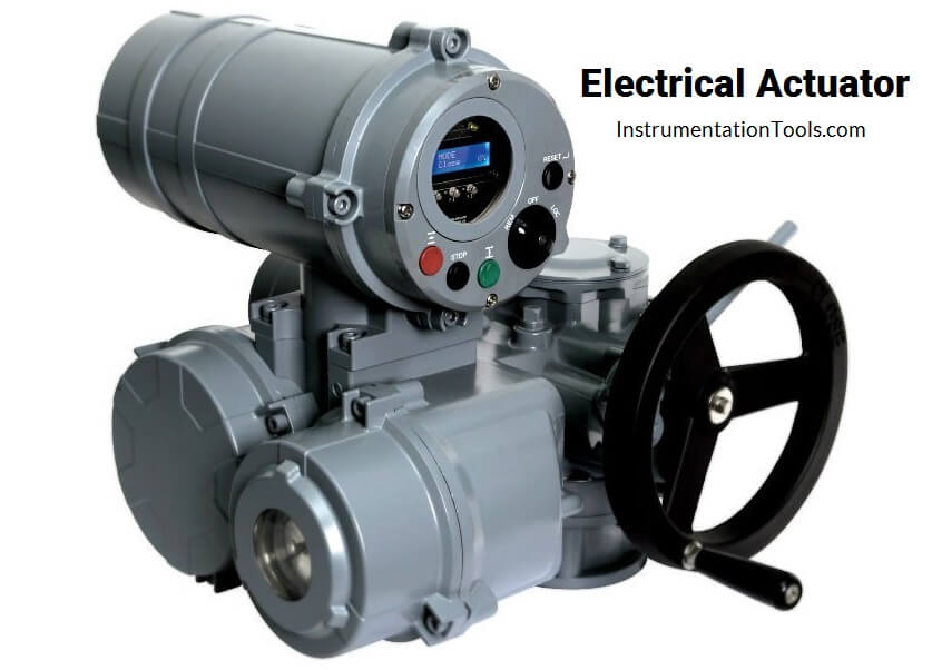
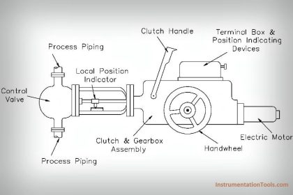
The electric actuator uses an electric motor to provide torque to operate a valve. They are quiet, non-toxic and energy efficient. However, electricity must be available, which is not always the case, they can also operate on batteries.
Electric Motor Actuator Parts
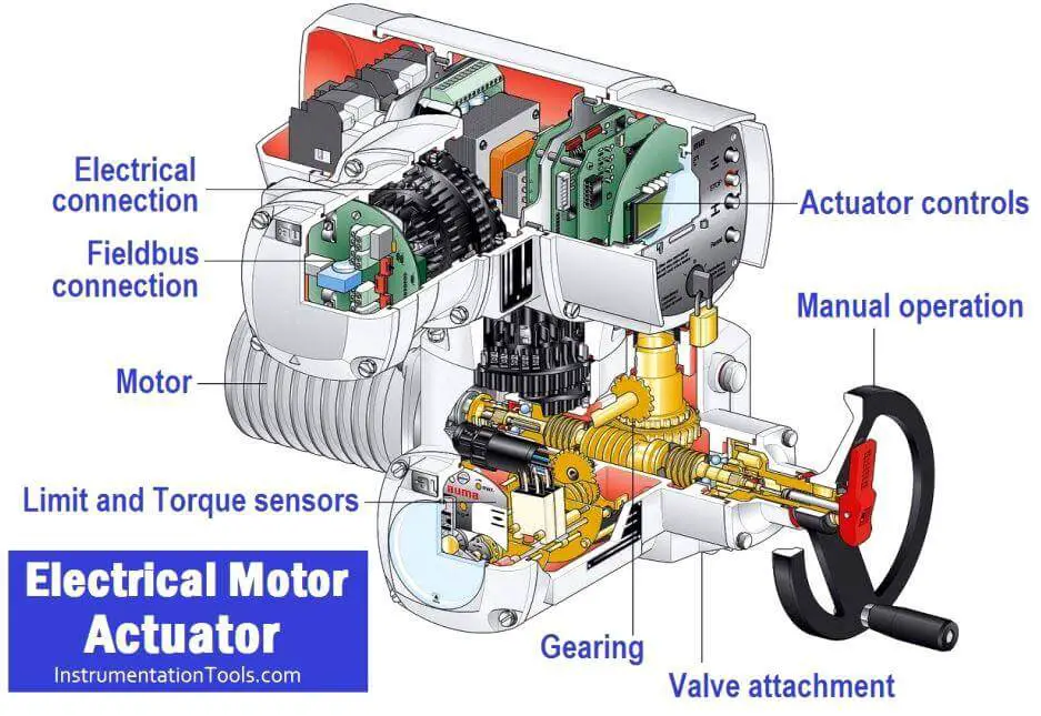
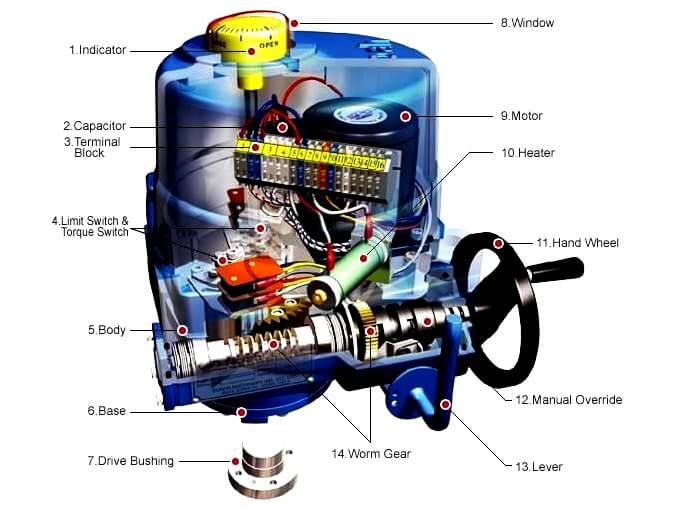
Motor
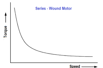
Robust asynchronous three-phase AC motors are mostly used as the driving force, for some applications also single-phase AC or DC motors are used. These motors are specially adapted for valve automation as they provide higher torques from standstill than comparable conventional motors, a necessary requirement to unseat sticky valves.
The actuators are expected to operate under extreme ambient conditions, however they are generally not used for continuous operation since the motor heat buildup can be excessive.
Limit and Torque Sensors
The limit switches signal when an end position has been reached. The torque switching measures the torque present in the valve. When exceeding a set limit, this is signaled in the same way.
Actuators are often equipped with a remote position transmitter which indicates the valve position as continuous 4-20mA current or voltage signal.
Gearing
Often a worm gearing is used to reduce the high output speed of the electric motor. This enables a high reduction ratio within the gear stage, leading to a low efficiency which is desired for the actuators.
The gearing is therefore self-locking i.e. it prevents accidental and undesired changes of the valve position by acting upon the valve’s closing element.
Valve attachment
The valve attachment consists of two elements. First: The flange used to firmly connect the actuator to the counterpart on the valve side. The higher the torque to be transmitted, the larger the flange required.
Second: The output drive type used to transmit the torque or the thrust from the actuator to the valve shaft. Just like there is a multitude of valves there is also a multitude of valve attachments.
Dimensions and design of valve mounting flange and valve attachments are stipulated in the standards EN ISO 5210 for multi-turn actuators or EN ISO 5211 for part-turn actuators. The design of valve attachments for linear actuators is generally based on DIN 3358.
Manual operation
In their basic version most electric actuators are equipped with a handwheel for operating the actuators during commissioning or power failure. The handwheel does not move during motor operation.
The electronic torque limiting switches are not functional during manual operation. Mechanical torque-limiting devices are commonly used to prevent torque overload during manual operation.
Actuator controls
Both actuator signals and operation commands of the DCS are processed within the actuator controls. This task can in principle be assumed by external controls, e.g. a PLC.
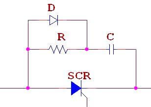
Modern actuators include integral controls which process signals locally without any delay. The controls also include the switchgear required to control the electric motor. This can either be reversing contactors or thyristors which, being an electric component, are not subject to mechanic wear.
Controls use the switchgear to switch the electric motor on or off depending on the signals or commands present. Another task of the actuator controls is to provide the DCS with feedback signals, e.g. when reaching a valve end position.
Electrical connection
The supply cables of the motor and the signal cables for transmitting the commands to the actuator and sending feedback signals on the actuator status are connected to the electrical connection.
The electrical connection can be designed as a separately sealed terminal bung or plug/socket connector. For maintenance purposes, the wiring should be easily disconnected and reconnected.
Fieldbus connection
Fieldbus technology is increasingly used for data transmission in process automation applications. Electric actuators can therefore be equipped with all common fieldbus interfaces used in process automation.
Special connections are required for the connection of fieldbus data cables.
