DP Transmitter Elevation and Suppression Corrections for Level Measurement
When installing a DP transmitter to measure liquid level, configuration of the transmitter often must include an adjustment for one of two conditions introduced by the mounting arrangement.
Elevated Span
The Lower Range Value (LRV) of the transmitter needs to be configured above 0.
Suppressed Span
The LRV of the transmitter needs to be configured below 0.

A brief discussion of how to make adjustments for elevation and suppression follows. Then two examples of the calculations needed to determine configuration parameters are given. Finally, a brief procedure that does not involve calculations is provided.
The range of the transmitter can be set anywhere, forward or reverse acting, as long as the following criteria are met:
LRL ≤ LRV ≤ URL
LRL ≤ URV ≤ URL
Span = [URV – LRV] ≥ Min Span
Note that the URL (Upper Range Limit), LRL (Lower Range Limit), and Min Span are transmitter dependent.
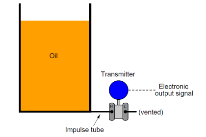
Transmitter Elevation Calculation Example
The below figure shows a sample transmitter installation.

1. Calculate the differential pressure as follows.
Pressure@DP = (H × SpG)High Side – (H × SpG)Low Side
where H = Height
2. Calculate the LRV when the tank is empty.
LRV = (120 x 1.0)High Side – (0 x 1.0)Low Side
LRV = +120 inH2O
3. Calculate the URV.
URV = LRV + Span
URV = +120 + 100
URV = 220 inH2O
Therefore, transmitter range should be 120 to 220 inH2O
Transmitter Suppression Calculation Example
The below figure shows a sample transmitter installation.

1. Calculate the differential pressure as follows.
Pressure@DP = (H × SpG)High Side – (H × SpG)Low Side
where H = Height
2. Calculate the LRV when the tank is empty.
LRV = (0 x 1.0)High Side – (100 x 1.0)Low Side
LRV = -100 inH2O
3. Calculate the URV.
URV = LRV + Span
URV = -100 + 100
URV = 0 inH2O
Therefore, transmitter range should be -100 to 0 inH2O
Source : Siemens Pressure Transmitter
Articles You May Like :
Closed Tank Remote Seal Capillary
Tank Interface Level Measurement
Process Variable to Percentage
Valve Pressure Drop Calculation
Transmitter Output in Percentage


Would like to ask how these articles can be downloaded. Many thanks to you Sir, this information is very helpful to aspiring young technical personal.
very good description
Thank you for those very important calculation for DP transmitters presented in a very simple and understandable way.
How to save or download those valuable techniques ?
thank you once again
Best regards.
Abdulkhaliq Albelushi
hii can you please tell what H2O SpG=1 means
Specific gravity of the liquid inside tank. Here it is assumed sg=1
thank you
dear, sir thank u very much for the calculation of level measurement
thank you very much
Merci beaucoup
Please how do you calebrate the level transimeter when it is showing default on URV and LRV and and it ends at 46% as the maximum.
check all the specification on HART and then adjust the SPAN at 0%..25%..50..75..100%
sir ,what is catch spot phenomenon in level transmitter?
Very good info
Boiler running time bed material level calculation