Inst ToolsInst ToolsInst Tools
  • Courses
  • Automation
    • PLC
    • Control System
    • Safety System
    • Communication
    • Fire & Gas System
  • Instrumentation
    • Design
    • Pressure
    • Temperature
    • Flow
    • Level
    • Vibration
    • Analyzer
    • Control Valve
    • Switch
    • Calibration
    • Erection & Commissioning
  • Interview
    • Instrumentation
    • Electrical
    • Electronics
    • Practical
  • Q&A
    • Instrumentation
    • Control System
    • Electrical
    • Electronics
    • Analog Electronics
    • Digital Electronics
    • Power Electronics
    • Microprocessor
  • Request
Search
  • Books
  • Software
  • Projects
  • Process
  • Tools
  • Basics
  • Formula
  • Power Plant
  • Root Cause Analysis
  • Electrical Basics
  • Animation
  • Standards
  • 4-20 mA Course
  • Siemens PLC Course
Reading: Differential Pressure Switch Principle
Share
Font ResizerAa
Inst ToolsInst Tools
Font ResizerAa
  • Courses
  • Design
  • PLC
  • Interview
  • Control System
Search
  • Courses
  • Automation
    • PLC
    • Control System
    • Safety System
    • Communication
    • Fire & Gas System
  • Instrumentation
    • Design
    • Pressure
    • Temperature
    • Flow
    • Level
    • Vibration
    • Analyzer
    • Control Valve
    • Switch
    • Calibration
    • Erection & Commissioning
  • Interview
    • Instrumentation
    • Electrical
    • Electronics
    • Practical
  • Q&A
    • Instrumentation
    • Control System
    • Electrical
    • Electronics
    • Analog Electronics
    • Digital Electronics
    • Power Electronics
    • Microprocessor
  • Request
Follow US
All rights reserved. Reproduction in whole or in part without written permission is prohibited.
Inst Tools > Blog > Pressure Measurement > Differential Pressure Switch Principle

Differential Pressure Switch Principle

Last updated: March 9, 2017 5:39 am
Editorial Staff
Pressure Measurement Switches
1 Comment
Share
3 Min Read
SHARE

The Differential Pressure Switch just like the pressure switch is a simple electro- mechanical device that operates on the basic principles of Levers and opposing forces. They are mainly used for sensing a difference in pressure between two points in a plant or system.

These elements are:

(a) Sensing element made either of bellows or diaphragm (metallic or elastomeric)
(b) A stable spring to determine the range set point and
(c) A snap-acting micro-switch available in a wide variety (SPDT, DPDT etc)

Operating Principle:

A differential pressure switch is designed to sense a difference in pressure between two pressure sources in the plant for control purposes. When the pressures from two different sources in a process are connected across the sensing diaphragm, metallic or elastomeric as the case may be, the pressure difference creates a force which then overcomes that of a pre-tensioned spring and in the process moves a balancing arm or mechanism to effect the minimal movement required to actuate the micro-switch(es) of the switch.

High and low pressures are applied on either side of the specially contoured sensing diaphragm. This design feature helps to eliminate errors due to a difference in area which is often a common problem present in twin element pressure differential switches.

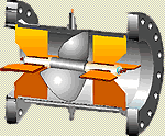
A particular design of the differential pressure switch is described below to illustrate the principle of operation. Please note that there are various variants of the switch from different manufacturers but the basic principle of operation remains the same.

Differential Pressure Switch Principle

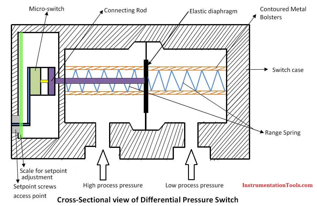
As shown in the diagram above, the pressure ports for high process pressure and low process pressure are separated by an elastic diaphragm. The difference in pressure that exist between the two ports causes axial movement (measuring travel) of the diaphragm against the measuring range spring. The differential pressure, which is proportional to the measuring travel, is transmitted by means of a connecting rod with little friction to the plungers of the micro-switch. The micro-switch contains the electrical contacts of the switch. The electrical contacts of the switch will actuate depending on the switch points or setpoints. Overpressure protection is provided by contoured metal bolsters for the elastic diaphragm.

The adjustment of the switch point or setpoint is made by setpoint screws accessible from the front of the differential pressure switch case. The graduated scales enable a relatively accurate adjustment of the switch points and indicate the setpoint that is momentarily adjusted.

In conclusion, the differential pressure switch essentially works on the basis of a difference in pressure between the high and low pressure ports. This difference in pressure is then converted into axial movement that is used to actuate the contacts of a micro-switch depending on the setpoint(s) of the differential pressure switch.

Don't Miss Our Updates
Be the first to get exclusive content straight to your email.
We promise not to spam you. You can unsubscribe at any time.
Invalid email address
You've successfully subscribed !

Continue Reading

Functions of Pressure Detectors
Pressure Gauge Problems
5 Valve Manifold Operation
DP Transmitter Applications
Ultrasonic Level Switch Working Principle
What are Impulse Lines? – Impulse Line Problems & Solutions
Share This Article
Facebook Whatsapp Whatsapp LinkedIn Copy Link
Share
1 Comment
  • Abdulkhaliq Albelushi says:
    March 18, 2017 at 2:52 am

    Thank you for those useful information.

    Reply

Leave a Reply Cancel reply

Your email address will not be published. Required fields are marked *

Stay Connected

128.3kFollowersLike
69.1kFollowersFollow
210kSubscribersSubscribe
38kFollowersFollow

Categories

Explore More

What is LVDT ?
Interview Questions on Pressure Measurement
Pressure Measurement Objective Questions
Differential Pressure Gauge Principle
Limit Switch Animation
Pressure Gauge Calibration according to Standard DKD-R-6-1
What is a Inductive Proximity Switch ?
Impulse Line – Purpose & Tapping Point Location

Keep Learning

Well Manometer Principle

Well Manometer Principle

Limit Switch Schematic

Basics of Limit switches

Pressure Transmitter

Pressure Transmitter Animation

pressure-switch-calibration-procedure

Pressure Switch Calibration Procedure

Flow Switch Principle

In-Line Flow Switch Working Principle and Animation

Differential Pressure Sensor Calibration

Differential Pressure Sensors Calibration Procedure

Principle of Elastic diaphragm gauges

Elastic Diaphragm Gauge Principle

Hand Switch Pressed Working Animation

Pushbutton switches and Types of Switches

Learn More

Basic AC Generator

AC Generator Parts

non-contact and guided-wave radar level transmitters

Radar Level Measurement

RTD Calculator : Calculate Temperature from Resistance

RTD Calculator : Calculate Temperature from Resistance

Bus Riser in Switchgear

Bus Riser in Switchgear

Firmware Version in Siemens PLC

What is the Firmware Version of a PLC? – Siemens PLC Hardware

Unbonded Strain Gauge Principle

Unbonded Strain Gauge Principle

Pressure Transmitter Troubleshooting Tips

Pressure Transmitter Troubleshooting Tips

Flapper nozzle system

Flapper Nozzle Questions

Menu

  • About
  • Privacy Policy
  • Copyright

Quick Links

  • Learn PLC
  • Helping Hand
  • Part Time Job

YouTube Subscribe

Follow US
All rights reserved. Reproduction in whole or in part without written permission is prohibited.
Welcome Back!

Sign in to your account

Username or Email Address
Password

Lost your password?